The following sections detail the conditions under which a setup is appropriate for various types of operations on various types of milling and turning machines. These sections say that a setup axis “would (if used) render accessible a GCD for an operation” as shorthand for the following:
-
Were the part to be oriented as specified by the setup axis (see Part Orientations), the GCD would have the required type of accessibility from a direction from which the tool can approach (see GCD Accessibility and Tool Orientations).
This section has the following subsections:
Non-rotational Setup Axes for 3- and 4-Axis Mill
Since a non-rotational setup axis points in the direction from which the tool approaches (when the part is oriented as specified by the setup axis), a non-rotational setup axis generally would (if used) render a GCD accessible for an operation when the following holds:
-
The GCD has the required accessibility (see GCD Accessibility and Tool Orientations) from the direction specified by the setup axis.
For example, a non-rotational setup axis would (if used) render a planar face accessible to a facing operation if the setup axis is normal (unobstructed) to the planar face.
The table below (which is essentially the same as the table in GCD Accessibility and Tool Orientations) shows when a non-rotational setup axis generally would (if used) make a GCD accessible for some basic types of machining operations on a 3- or 4-axis mill:
|
Setup axis/GCD relationship |
Facing |
Side Milling |
Contouring |
Hole Making |
|---|---|---|---|---|
|
Planar Face |
Normal (unobstructed) |
Parallel (unobstructed) |
Oblique (unobstructed) |
|
|
Curved Wall |
|
Parallel (unobstructed) |
Oblique (unobstructed) |
|
|
Curved Surface |
|
|
Oblique (unobstructed) |
|
|
Hole |
|
|
|
Parallel (unobstructed) or Parallel obstructed |
See also Multiple Approach Surface Finishing.
Note also that a 4-Axis mill that supports machining while its rotational axis is turning can face a curved wall provided that the curved wall is convex.
Rotational Setup Axes for 4-Axis Mill
On a 4-axis mill, the spindle is perpendicular to the axis of rotation, so a rotational setup axis is perpendicular to the direction from which the tool approaches. This means that a rotational setup axis on a 4-axis mill generally would (if used) render a GCD accessible to an operation if the following holds:
-
The GCD has the required accessibility (see GCD Accessibility and Tool Orientations) from some tool orientation that is perpendicular to the setup axis.
For example, a rotational setup axis on a 4-axis mill would (if used) render a planar face accessible to a facing operation if the setup axis is perpendicular to some tool orientation that is normal (unobstructed) to the planar face.
The table below indicates when a rotational setup axis generally would (if used) make a GCD accessible for some basic types of machining operations on a 4-axis mill:
|
Setup axis/GCD relationship |
Facing |
Side Milling |
Contouring |
Hole Making |
|---|---|---|---|---|
|
Planar Face |
Perpendicular to a tool orientation that is normal (unobstructed) |
Perpendicular to a tool orientation that is parallel (unobstructed) |
Perpendicular to a tool orientation that is oblique (unobstructed) |
|
|
Curved Wall |
|
Perpendicular to a tool orientation that is parallel (unobstructed) |
Perpendicular to a tool orientation that is oblique (unobstructed) |
|
|
Curved Surface |
|
|
Perpendicular to a tool orientation that is oblique (unobstructed) |
|
|
Hole |
|
|
|
Perpendicular to a tool orientation that is parallel (unobstructed) or Parallel obstructed |
See also Multiple Approach Surface Finishing.
Setup Axes for 5-Axis Mill
Like a 4-axis mill, a 5-axis mill can rotate the part. A 5-axis mill can also tilt the part or the spindle up to a maximum tilt angle, which is specified by the machine attribute maxTiltAngle.
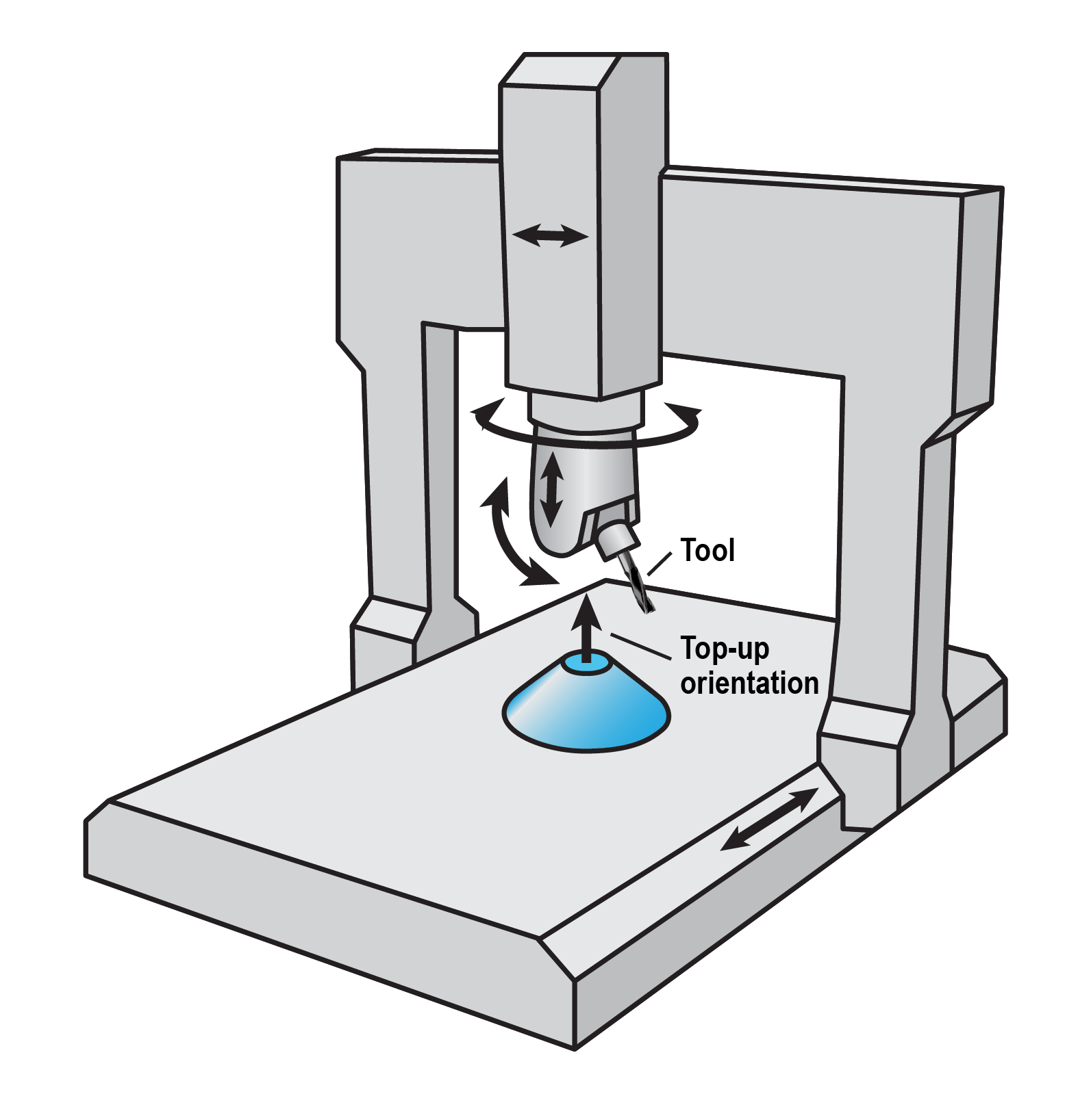
On the 5-axis mill machines currently supported by aPriori starting point Digital Factories, the spindle is parallel to the axis of rotation, when the machine table or spindle is not tilted. So a setup axis on a 5-axis mill generally would (if used) render a GCD accessible to an operation if the following holds:
-
The GCD has the required accessibility from some tool orientation that is within maxTiltAngle of the setup axis.
For example, a setup axis on a 5-axis mill would (if used) render a planar face accessible to facing if the setup axis is within maxTiltAngle of some tool orientation that is normal (unobstructed) to the planar face. The table below shows when a rotational setup axis generally would (if used) make a GCD accessible for some basic types of machining operations on a 5-axis mill:
|
Setup axis/GCD relationship |
Facing |
Side Milling |
Contouring |
Hole Making |
|---|---|---|---|---|
|
Planar Face |
Within maxTiltAngle of a tool orientation that is normal (unobstructed) |
Within maxTiltAngle of a tool orientation that is parallel (unobstructed) |
Within maxTiltAngle of a tool orientation that is oblique (unobstructed) |
|
|
Curved Wall |
|
Within maxTiltAngle of a tool orientation that is parallel (unobstructed) |
Within maxTiltAngle of a tool orientation that is oblique (unobstructed) |
|
|
Curved Surface |
|
|
Within maxTiltAngle of a tool orientation that is oblique (unobstructed) |
|
|
Hole |
|
|
|
Within maxTiltAngle of a tool orientation that is parallel (unobstructed) or Parallel obstructed |
See also Multiple Approach Surface Finishing.
Note also that Ruled Curved Surfaces can be Side Milled by aPriori’s supported type of 5-Axis Mill provided that the maximum inclination of the ruled surface does not exceed the maximum tilt angle.
Turning Axes for 3-Axis Lathe
On a 3-axis lathe, the spindle of the live tooling (mill cutters that can be mounted to the machine and spun by independent motors) can be either perpendicular or parallel to the machine’s turning axis. This means that a turning axis on a 3-axis lathe generally would (if used) render a GCD accessible to an operation if the following holds:
-
The GCD has the required accessibility from some tool orientation that is perpendicular or parallel to the turning axis.
For example, a turning axis on a 3-axis lathe would (if used) render a planar face accessible to a facing operation if the turning axis is perpendicular to some tool orientation that is normal (unobstructed) to the planar face. The table below indicates when a turning axis generally would (if used) make a GCD accessible for some basic types of machining operations on a 3-axis lathe:
|
Turning axis/GCD relationship |
Facing |
Side Milling |
Contouring |
Hole Making |
|---|---|---|---|---|
|
Planar Face |
Perpendicular or parallel to a tool orientation that is normal (unobstructed) |
Perpendicular or parallel to a tool orientation that is parallel (unobstructed) |
Perpendicular or parallel to a tool orientation that is oblique (unobstructed) |
|
|
Curved Wall |
|
Perpendicular or parallel to a tool orientation that is parallel (unobstructed) |
Perpendicular or parallel to a tool orientation that is oblique (unobstructed) |
|
|
Curved Surface |
|
|
Perpendicular or parallel to a tool orientation that is oblique (unobstructed) |
|
|
Hole |
|
|
|
Perpendicular or parallel to a tool orientation that is parallel (unobstructed) or Parallel obstructed |