Use the Tolerance Defaults tab to set the default tolerance policy applied when a CAD file is imported or updated:
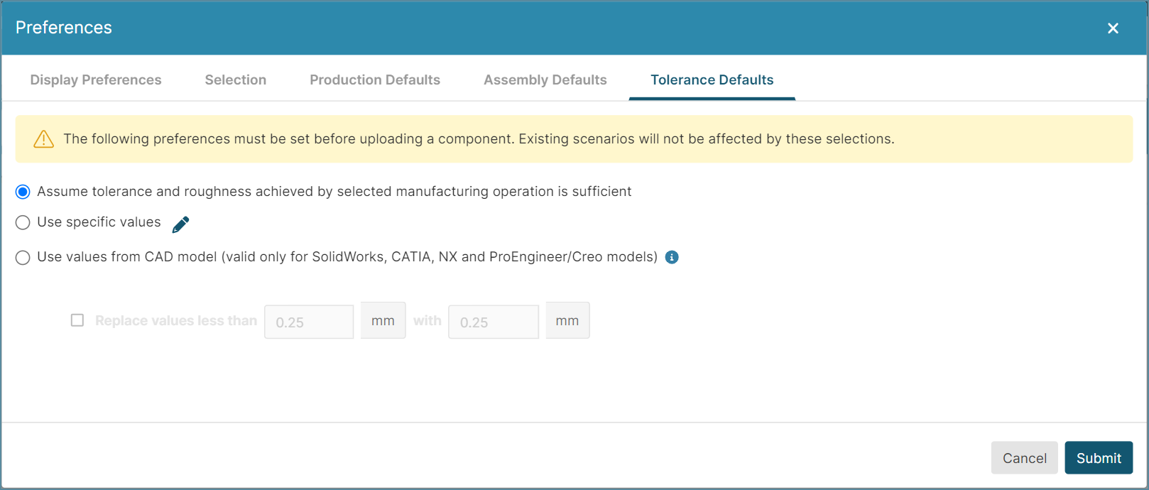
The options are:
-
Assume tolerance and roughness achieved by the selected manufacturing operation is sufficient: (Default option) aP Design then assumes that selected processes have sufficient tolerance capabilities to manufacture each GCD in the part. Also, aP Design does not include any tolerance or roughness PMI from uploaded models in the new component scenario.
-
Use specific values: aP Design uses manually specified default tolerance and surface roughness for new components.
-
To view or edit the Tolerance settings, click the edit button,
 . Then, in the Tolerances Overrides dialog, review or update the settings.
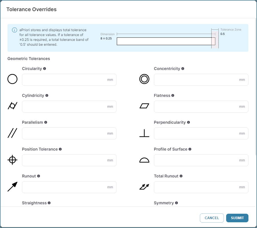
DEPENDENCY: If this option is selected, in the Design Guidance Explorer, on the Tolerances tab, in the table in the right pane, the Source of the tolerance is Policy.
Note: aP Design stores and displays tolerance values only as the total tolerance. For example, a tolerance of ±0.25, is expressed as a tolerance of 0.5.
-
-
Use values from CAD model: aP Design uses semantic attributes for tolerance and roughness requirements that it extracts when importing the CAD model.
Import limitations
aP Design can extract tolerance and roughness requirements from CAD files only:
-
If the requirements are included as semantic attributes in a supported CAD file. For information supported CAD file formats, see the aPriori Cloud System Requirements documentation.
-
When the CAD file is being imported.
-
If the Use values from CAD model option is selected.
DEPENDENCY: If this option is selected, in the Design Guidance Details panel, on the Tolerances tab, in the table in the right pane, the Source of the tolerance is CAD.
-
Replace values less than x with y: aP Design replaces any tolerance that is tighter than a specified minimum tolerance (x, in the default unit for length, with a specified replacement tolerance (y, in the default unit for length) where y ≥ x. This option is useful for overwriting overly tight tolerance requirements that are specified in CAD models.
For this option, you can edit both the boundary condition (x) and the replacement value (y).
DEPENDENCY: This option is applicable only if Use values from CAD model is selected as the default tolerances setting for new components.