New Sheet Metal - Roll Forming Cost Model
aPriori 2022 R1 provides a new cost model for the sheet metal roll forming manufacturing process, addressing high demand for this cost model among the aPriori customer base. This cost model is separately licensed and accessed via the new Sheet Metal - Roll Forming process group.
Roll Forming is a high-speed method of progressively bending coiled metal into a uniform cross-section. As shown in the conceptual image below, a sheet metal strip passes through multiple sets of roll dies. Each set incrementally forms the metal until the final cross-section is achieved after passing through all of the roll die sets. The number of roll die sets depends on the complexity of the cross-section, the material thickness, and tolerance specifications. The full collection of roll die sets required to form the finished profile is called the Roll Forming Mill.
Figure: Roll forming mill
Sheet Metal Roll Forming is used broadly across industry sectors and part types. Some key benefits of the Roll Forming process include:
- High production volumes
- Supports a wide range of materials
- Low scrap
- Close tolerances
- Superior surface finish
- Long tool life
- Can make very long parts
- Cost and weight reduction (for example, compared to extrusion or stamping processes)
Additionally, parts coming off the roll forming line typically are fully finished or very-near finished after part cut-off, eliminating most or all off-line processing. This diagram shows typical processes in a Roll Forming line.
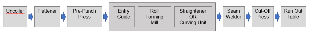
Figure: Roll forming line
- An Uncoiler feeds the coil material stock into the line. The sheet metal stock passes through a Flattener to remove any bow from the material.
- The line typically contains one or more Punch Presses to create any holes, cutouts, and embossments in the material.
- In this diagram, we show just a Pre-Punch Press, meaning the punch is inline BEFORE the roll forming mill. Pre-punching is used for parts with standard tolerance requirements that allow the holes and features to be punched in the flat strip. But there may be additional inline punches positioned after the Roll Forming Mill and even BETWEEN roll dies, if tighter tolerances are specified for the punched features. These are referred to as Post-Punch and Mid-Punch presses, respectively.
- The sheet metal stock then passes through the Roll Forming Mill. After the last Roll Die set, there is typically a Straightener unit. However, a Curving Unit can be used to bend the part as an inline operation.
- Curving Units are appropriate for making a single profile bend with a constant radius which extends the entire length of the finished part. Other bend types, such as those with varying bend radii or those that are isolated to only a section of the part, require a post-cutoff (offline) bending process such as CNC Profile Bending or Rotary Draw bending.
- If the desired cross-section is closed, that can be achieved by using one of several in-line Seam-Welding processes to fuse the two open edges together. The aPriori cost model includes the choice of High Frequency Induction (HFI) Welding, Rotary Spot Welding, Laser Welding, and TIG Welding processes.
- aPriori provides manufacturing cost models for Integrated High Frequency Induction (HFI) Welding, Integrated Rotary Spot Welding, Integrated Laser Welding, and Integrated TIG Welding. Integrated HFI Welding is assigned by default for parts with closed cross-sections but any welding process can be assigned manually to any part.
- A Cut-Off Press is used to cut the parts to length.
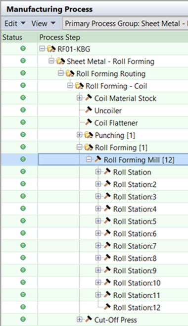
aPriori's Sheet Metal - Roll Forming routing includes all the above processes. Some processes are optional and will be included only if needed based on part geometry and/or tolerance requirements. For example, a Seam Welding process will be included only if the part has a closed cross-section. A Curving unit (additional Roll Dies for bending the part along its length, after the cross-section has been formed) will be included only if the part includes a single constant-radius bend along its entire length; an offline CNC Profile Bend process will be included for other bends along the length of the part. Mid-Punch Press or Post-Punch Press will be included only if there are tighter-than-standard tolerances on one or more punched features.
Since Roll Forming involves a continuous coil fed line, the slowest process in the routing limits the overall line speed and therefore part cycle time. The aPriori Sheet Metal - Roll Forming cost model determines the maximum possible operating line speed for each of the processes included in the routing, given the part's geometry and tolerance requirements. In the Part Details tab, aPriori displays some custom outputs which indicate the maximum line speed capacity for the chosen Roll Forming Mill and also indicate which process in the line is the limiting factor. In the example below, the Roll Forming Mill could achieve speeds of over 1 meter per second, but the Punch Press is the limiting factor; it can achieve an Operating Line Speed of only 338.67 mm/second which is therefore the speed of the entire line.
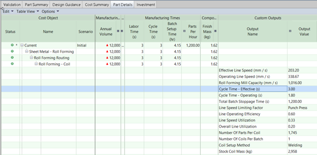
Figure: Operating line speed
Also note that aPriori also calculates the Effective Line Speed and Effective Cycle Time, as well as the Operating Line Speed and Operating Cycle Time. If the line needs to be stopped periodically, for example, to change the sheet metal coil, replace worn punch tools or cutoff blades, or periodically band finished parts and empty the parts bin, then that downtime is considered to produce the final Effective Line Speed. In the example above, the Effective Line Speed is 203.20 mm/s (less than 2/3 of the Operating Line speed) and the Effective Cycle Time is 3.00 seconds (compared to the faster Operating Cycle Time per part of 1.80 seconds). There are process setup options available on each process to modify the assumptions which contribute to batch (line) stoppage and effective line speed, such as Die Changeover time required for the punch press and Die Tooling Material which contributes to tool lifetime estimates.
The Geometric Cost Drivers (GCDs) extracted for the Sheet Metal - Roll Forming process group include typical sheet metal GCDs such as the Blank (size of the raw material coil or strip stock required to make a finished part), SimpleHoles and ComplexHoles (round and non-round interior holes, respectively), and StraightBends (bends that are parallel to the direction of travel and are formed as the part passes through the roll die sets). Roll Forming parts also may include Cutout GCDs -- notches which intersect the blank edge, rather than being an enclosed interior hole. In addition, Roll Forming parts will have a Cross-Section GCD, which shows the final formed cross se
The aPriori Roll-Forming cost model analyzes the GCDs found on the part and considers key inputs such as tolerance specifications to determine the specific processes and tooling included in the routing. Tolerances either can be imported from the CAD model (requires the Advanced PMI license) or entered directly in aPriori. Tolerances can be entered for individual GCDs if desired. Alternatively, process setup options Cross Section Tolerance and Inline Punching Feature Tolerance enable the user to specify the tolerances for the part profile and all punch features for which tolerance is not individually specified.
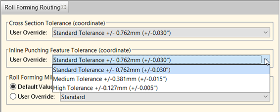
Figure: Roll forming routing
By default, aPriori assumes a "standard tolerance" for both the cross-section profile and punched features. Tighter tolerances on the cross section profile will cause extra finishing roll die sets to be added to the Roll Forming Mill, increasing tooling cost. Tighter tolerances on punched features will cause a Mid-Punch Press or Post-Punch Press to be added to the routing. This will increase process costs due to both the additional machine overhead for the additional presses, and lower cycle times due to the slower line speed capacities of Mid- and Post-Punch presses.*
Note: *The Cutoff Press, and any Mid-Punching or Post-Punching presses, use accelerated dies so the die is actually moving when it punches or cuts the part. Physical limits on how quickly the die can accelerate and what speeds can be attained are one of the main constraints on the overall line speed. aPriori calculates the achievable speed of the cut-off die and any post-forming punch dies, given the mass of the die and the distance they have to accelerate (which is the length of the part.) In contrast, Pre-Punching typically is performed with a stationary die, with buffer loops of material on either side of it. This is the preferred approach as stationary dies can be larger and punch greater numbers of features at once, without causing a significant reduction in line speed. However, tolerance requirements may drive the need for Mid- or Post-Punch presses and therefore slower line speeds.
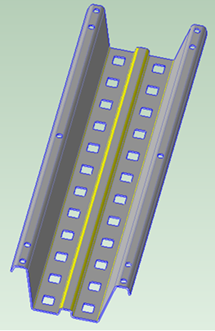
StraightBend GCDs orthogonal to the part cross-section are assigned to the Roll Forming Mill process. The total number of Roll Die Sets and the order of bending that is estimated by aPriori depends on factors such as the angles of the bends, number of distinct bends in the cross-section profile, the distance between these parallel bends, and the location and symmetry of the bends along the profile. Typically, the incremental bending that can be achieved by a single roll die set does not exceed 15 degrees per bend -- so forming a 90-degree bend would require a series of six roll die sets. For symmetrical parts, pairs of symmetric bends are formed simultaneously on the same roll die sets -- as shown in the first picture in this section. Also, bends that are located close together, such as a set of four bends comprising a rib/stiffening feature, typically are made simultaneously over a shared set of roll dies. In terms of order of bending, bends that are located in the center of the part tend to be made first, as they require material to be drawn inward.
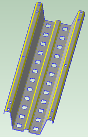
Consider the part shown below as an example. aPriori has determined that 12 Roll Die Sets are required to form this cross-section:
|
|
Figure: Cross section with 12 roll die sets
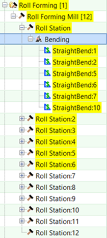
If we inspect which bends are made on the individual stations (that is Roll Die Sets), we see the four bends comprising the central rib feature are formed over the first six stations, and so are the adjacent bends on either side of the rib that fold up the "wings" of this part.
|
|
Figure: 4 bends over first 6 stations
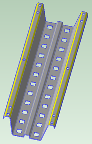
The two outermost bends on each side of the part are made next, over stations 7 through 11:
|
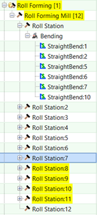
|
Figure: Outermost bends: stations 7 - 11
And the final 12th set of roll dies is for finishing the profile. As noted earlier, if close tolerances are specified for the cross-section profile, additional finishing stations will be added.
The Roll Forming Tooling Report (available via the Reports >Spreadsheet Reports menu) displays a detailed breakdown of the cost of the Roll Die Sets, based on the number of rolls, the size of the rolls (estimated from part geometry) and the tooling material, which is assumed to be AISI 4140 Steel by default. The report also provides detailed breakdowns of the tooling for the Punch press(es) and Cut-off press, similar to what is provided in the tooling report for other sheet metal process groups. The report consists of two Excel worksheets named Roll Forming - Summary and Roll Forming - Detail.
Known Limitations
- If the CAD model of the part has a closed cross-section, indicating a part that is intended to be seam-welded after the cross-section profile is roll-formed, aPriori may determine a "virtual seam location" that is different than where the seam would be located in actual manufacturing practice. aPriori currently assumes the seam is located at one end of the longest edge in the cross section profile, and does not attempt to choose a seam location which allows for balanced bending and accessibility of the seam for welding. To work around this limitation, the seam should be modeled explicitly in the CAD model as a small gap in the cross-section profile that extends the entire length of the part.
- The Sheet Metal - Roll Forming cost model does not support surface-only CAD models. To work around this limitation, modify the CAD model and "thicken" the surfaces so that you have a solid model of the part which can be cost in aPriori.