aPriori 2022 R1 provides multiple enhancements to the Assembly process group geometry extraction and assembly process cost model logic to enable more automated and accurate manufacturing and cost estimation of various assembly processes including Welding, Adhesive Bonding, Fay Sealing and any associated Clamping operations. These enhancements are described as follows:
- New Assembly GCDs: Contact Regions and Contact Groups
- Relationship between Weld GCD and Contact Region GCDs provides information about which components are welded together
- Improved estimates of Clamping for Welding and Adhesive Bonding processes
- Improved accuracy of Adhesive Bonding process cycle time and cost
- Improved accuracy of Fay Sealing process cycle time and cost
- Updated Pick and Place Load Times for Assembly Subcomponents
- Welding cycle time estimates now include time for Operator Repositioning
- Welding cost model updates for Assembly Reorientation
- Creo Welds now are available for users not connected to Creo
New Assembly GCDs: Contact Regions and Contact Groups
Two new types of Assembly GCDs now are extracted to capture and organize the regions where assembly subcomponents are in contact with one another and enable support for more accurate estimates of assembly joining operations.
A Contact Region represents a single continuous area of contact between two parts. A Contact Group is a collection of one or more Contact Regions which represent all the areas where two parts are touching. In the example below, Part B contacts Part A in two places, so there are 2 Contact Regions in the Contact Group for Parts A and B.
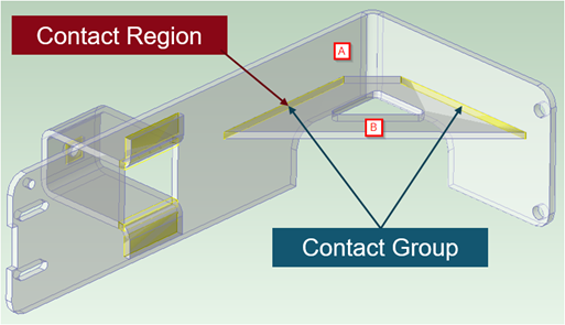
Figure: Contact Region and Contact Group
Contact Region GCDs include properties such as Area and Perimeter, which now are leveraged by various assembly process cost models to estimate more accurately the cycle times and costs for various assembly joining processes.
aPriori respects the assembly hierarchy as reflected in the CAD model. Contact Regions and Groups are split into two categories: ‘Top Level’ and ‘Lower Levels’. 'Top Level' Contact Regions are those which exist between Level 1 subcomponents, that is, between immediate children of the assembly. 'Lower Level' Contact Regions are those which exist between subcomponents at levels 2 and below, i.e. they represent places where parts touch within subassemblies. This distinction allows aPriori to consider that an entire subassembly is brought into the top level assembly as one subcomponent, and therefore considers its size and weight appropriately. This also gives the user a cleaner workflow as the convention is to define assembly operations only between the immediate children, and to open subassemblies in their own tab to perform assembly operations on them. If the CAD file has been modelled with a 'flat' hierarchy, aPriori will simply treat each individual CAD part as being assembled individually, which may not reflect reality.
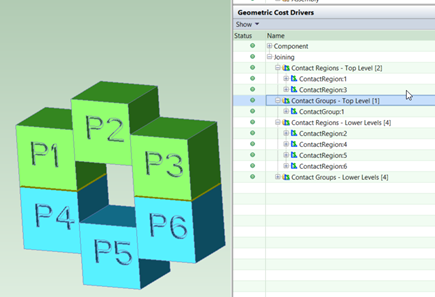
Figure: Top levels and lower levels split
The time required to open an Assembly CAD model for the first time and initialize a cost will increase slightly, since now aPriori analyses how components contact each other. In most cases, this increase in Assembly GCD extraction time is insignificant (a few seconds or less). If desired, extraction of Contact Region and Contact Group GCDs can be disabled by setting the Assembly process group site variable enableContactAnalysis to false.
Relationship between Weld GCD and Contact Region GCDs provides information about which components are welded together
aPriori now creates 'Lies On' relationships in order to indicate that a Weld GCD is placed on an edge which is adjacent or close to a Contact Region where two assembly components touch. This provides information about the specific components joined by Welding so that the cost model can calculate more accurate estimates for supporting operations such as Clamping.
Lies On relationships between Weld GCDs and Contact Region GCDs are created both for welds created in aPriori ("virtual welds") and for welds imported from Creo CAD models ("ProWelds"). A Lies On relationship will be created if the distance between the Weld and the Contact Region is within the threshold set by the site variable maxDistanceFromWeldToRegionMm. By default this variable is set to 10 mm rather than zero to support both welds defined in Creo (“ProWelds”) and welds defined in aPriori (“Virtual Welds”). Specifically, fillet welds defined in Creo may be represented as an angled surface located some distance (the design throat) away from the joint where two parts mate; this threshold allows aPriori to associate the Creo Weld with the nearest joint, or Contact Region. Customers who use only Virtual Welds, and who find that their Virtual Welds are being related incorrectly, can lower the value of this site variable to zero. This means that the relationship will exist only if the Weld is placed directly on the Contact Region, which is good practice.
Improved estimates of Clamping for Welding and Adhesive Bonding processes
The Clamping operation now is assigned to Contact Group GCDs not Subcomponent GCDs, and is included automatically when Welding or Adhesive Bonding processes are included for an assembly.
The Pick & Place Clamping operation now is applied automatically to Contact Group GCDs when there is a Weld GCD located on one or more edges of any Contact Region within that group (as defined by the Lies On relationship described above). The clamping cycle time is determined based on the estimated number of clamps required, and an assumed time to apply each clamp. The number of clamps required for each welded contact region is the number required to cover the length of the contact region plus the number required to cover the width of the contact region. By default, clamp spacing is assumed to be 6 inches (152.4 mm). Clamping can be specified as either Manual (placed individually by an operator) or Automated (applied by hydraulic actuators). By default, manual clamping is assumed for manual welding and adhesive bonding processes, and automated clamping is assumed for robotic welding processes. A clamping time of 10 seconds per manual clamp and 4 seconds per automated clamp is assumed. Clamp spacing and application times can be modified in the lookup table clamps. This table also provides settings to enable or disable different types of clamping for manual vs robotic welding processes.
Several process setup options provide the user with the ability to override the Type of Clamp Utilized (Manual vs Automatic), the Time to Clamp and Unclamp calculated for an individual Contact Group (i.e. pair of components), or even the Time to Clamp and Unclamp All Welded Subcomponents for the entire assembly. Users also can specify whether welded components are clamped only once (for both tacking and welding) or twice (once each for tacking and welding).
Note: If you upgrade to use the newest version of the Assembly cost model (CMV 170), there is an impact on some Assembly scenarios which were created in previous versions of aPriori. Specifically, older Assembly scenarios which included manually assigned Clamping operations no longer will include these operations, if they are migrated or imported into aPriori 2022 R1 and re-costed with the latest version of the Assembly cost model. This is because the Clamping operation which was assigned previously to Subcomponent GCDs no longer exists in the newer cost model version, as Clamping operations now are defined for Contact Group GCDs).
The recommended workflow is to re-extract GCDs from the original CAD file to generate the Contact Region GCDs; Clamping operations now will be assigned automatically if Welds are present. Additionally, the process setup option Time to Clamp and Unclamp All Welded Subcomponents is available on the Pick & Place process for adding or adjusting clamping estimates if desired.
Prior to 22.1, the lookup table ‘xtraLoadTime’ provided a fixed additional time for clamping based on the weight of the component. In the newest Assembly cost model version introduced in aPriori 2022 R1, this table no longer is used for Subcomponent clamping, but is still present in the cost model as it supports Assembly Plastic Molding logic, and for backwards compatibility.
Improved accuracy of Adhesive Bonding process cycle time and cost
Adhesive Bonding now can be applied to specific mating assembly components and is estimated more mechanistically and accurately. The Adhesive Bonding process now is controlled by applying bonding operations to Contact Region GCDs, which automatically also includes corresponding Clamping operations.
Users now apply Adhesive Bonding to the new Contact Region GCDs via the Operation Sequence Selection window (in the same way as they assign Mechanical Assembly Operations). aPriori estimates a time to apply the adhesive, based on the area of the Contact Region and an Application Rate defined in the Adhesive Bonding machine table. By default aPriori assumes that adhesive is applied to the entire area of a Contact Region, but users can adjust this assumption using the process setup option Bonded Area (expressed as a percentage). A degreasing time also is included, based on the same area and a degreasing rate (controlled by the cost model variable, degreaseApplicationRate). By default aPriori also assigns a clamping operation when Adhesive Bonding is applied, although this can be excluded if desired. The logic of the Clamping operation used for Adhesive Bonding is shared with the Clamping operation which is used withwelding, for consistency.
Previously, Adhesive Bonding was applied in the top level routing to the entire assembly, and the bonded area was assumed as a percentage of the total surface area of the assembly itself (10% by default). The new method provides a much more usable and mechanistic way of estimating the times and cost associated with the Adhesive Bonding process.
Note: If you upgrade to use the newest version of the Assembly cost model (CMV 170), there is an impact on Assembly scenarios defined in earlier releases of aPriori which include Adhesive Bonding operations. If these older scenarios are migrated or imported into aPriori 2022 R1 and cost using the latest Assembly cost model version, Adhesive Bonding cycle time estimates will revert to 0 seconds. This is due to the updates describe above, as Adhesive Bonding estimates now rely on the areas of the Contact Region GCDs which do not exist in older saved scenarios. The recommended workflow is to re-extract GCDs from the original CAD file to generate Contact Region GCDs and then assign Adhesive Bonding operations to the relevant Contact Regions. If this is not possible, the Adhesive Bonding process contains a process setup option Total Area Being Bonded into which users can enter an estimated area to generate an Adhesive Bonding cycle time and cost estimate.
Improved accuracy of Fay Sealing process cycle time and cost
Fay Sealing now can be applied to specific mating assembly components and is estimated more mechanistically and accurately. The Fay Sealing process is now controlled by applying sealing operations to Contact Region GCDs, which results in a more mechanistic and accurate estimate.
Users now assign Fay Sealing to the new Contact Region GCDs via the Operation Sequence Selection window (in the same way as they assign Mechanical Assembly Operations). aPriori estimates a time to apply the seal, based on the area of the Contact Region and an Application Rate defined in the Fay Sealing machine table. By default aPriori assumes that the entire area of a Contact Region is sealed, but users can adjust this assumption using the process setup option Sealed Area (expressed as a percentage). A degreasing time also is included, based on the same area and a degreasing rate (controlled by the cost model variable, degreaseApplicationRate).
Previously, Fay Sealing was applied in the top-level routing to the entire assembly, and the seal area was assumed as a percentage of the total surface area of the assembly itself (10% by default). The new method provides a much more usable and mechanistic way of estimating the times and cost associated with the Fay Sealing process.
Note: If you upgrade to use the newest version of the Assembly cost model (CMV 170), there is an impact on Assembly scenarios defined in earlier releases of aPriori which include Fay Sealing operations. If these older scenarios are migrated or imported into aPriori 2022 R1 and cost using the latest Assembly cost model version, Fay Sealing cycle time estimates will revert to 0 seconds. This is due to the updates describe above, as Fay Sealing estimates now rely on the areas of the Contact Region GCDs which do not exist in older saved scenarios. The recommended workflow is to re-extract GCDs from the original CAD file to generate Contact Region GCDs and then assign Fay Sealing operations to the relevant Contact Regions. If this is not possible, the Fay Sealing process contains a process setup option Total Area Being Sealed into which users can enter an estimated area to generate a Fay Sealing cycle time and cost estimate.
Updated Pick and Place Load Times for Assembly Subcomponents
Load times for Assembly Subcomponents now account for both part size and mass, and allow for specifying varying numbers of operators and types of equipment.
The component handling time lookup table componentLoadTime, which determines the time required to place an assembly component in the fixture, has been updated to account for both component size and mass and size. Previously only mass was considered. Now, if a component is over a certain size, regardless of mass (or over a certain mass, regardless of size) longer times and potentially additional operators and therefore labor costs will be associated with the positioning of the component. Where previously the table had two determining columns (weight and time), it now includes a max dimension column. It also includes a column to describe equipment used to load the part. For simplicity, equipment is categorized into classes: No Equipment, Level 1 (representing unpowered lifting equipment like hoists), Level 2 (representing small, powered devices like hoists and winches), and Level 3 (representing large, powered devices such as gantries and cranes). Another column accounts for the number of operators required for components of a given size and weight range; larger and heavier components require multiple operators. Previously all assembly operations were assumed to be carried out by one operator. This lookup table can be configured easily by Digital Factory Managers if desired.
As a result of these changes, the number of operators required now is considered at the operation level rather than the process level. The process setup option Number of Operators no longer is available on the Pick & Place process. Instead a new process setup option Time to Load All Subcomponents is available for users who wish to override aPriori's estimates.
Welding cycle time estimates now include time for Operator Repositioning
Welding cycle time estimates now account for the need for an operator to reposition while laying longer welds, based on an assumed operator reach. Previously aPriori accounted for re-positioning time between distinct welds, but not during an individual weld.
Weld cycle time calculations include updated estimates of operator positioning time and account for the repositioning needed for longer welds. Each weld will have an initial positioning time, plus an additional positioning time for each instance that aPriori estimates the operator will need to stop to reposition before continuing to lay the weld bead. This is based on an assumed Welder Reach value which is specified in the machine table for the welding process (by default, 6 inches/152.4mm). The time required to reposition is specified by the Gun Placement Time machine field, which was increased from 2 to 10 seconds.
Note: This value should be updated manually for customer machines in customer Digital Factories, when upgrading to the latest Assembly cost model.
As a result of this enhancement, the cycle time for welds shorter than 6 inches will increase by 8 seconds (due to the increase from 2 to 10 seconds for the initial positioning time), compared to the previous release of aPriori. Welds longer than 6 inches will increase by 10 seconds for every 6 inches of their length.
Welding cost model updates for Assembly Reorientation
Users now can specify a number of times to reorient an assembly during the Welding Process and specify whether the reorientation is performed manually or by use of a powered rotating fixture.
The process setup option Number of Reorientations enables users to specify whether it is necessary to reorient the assembly after fixturing and during the welding process, for example to apply welds to joints which are not accessible from the original orientation. This value is not estimated automatically by aPriori and is set to zero reorientations by default.
Digital Factory Managers can set this default to a different number using the cost model variable defaultNumberWeldingReorientations.
The reorientation time is determined by the componentLoadTime lookup table based on the assembly size and weight. Digital Factory Managers can configure these times with values more specific to their company's part types if needed.
Creo Welds now are available for users not connected to Creo
Weld features defined in the Creo CAD system and imported into aPriori when connected to Creo now are stored in aPriori and available for non-Creo-connected users.
Creo weld features extracted as Pro Weld GCDs via the aPriori-Creo Direct Integration mode now will be stored and retained in the aPriori scenario so they can be accessed by aPriori users who are not connected to Creo. Previously, Creo Welds disappeared when the scenario subsequently was opened in "CAD-Independent" (CAD-I) mode, so the cycle times and costs for these welds no longer were estimated. This enhancement improves workflow and collaboration between design engineers who run aPriori connected to Creo and other users such as Cost Engineers or Sourcing specialists who run aPriori standalone.