aPriori Professional 2022 R1 SP1 provides a new Multi-Spindle Machining cost model and enhancements to existing Multi-Spindle cost models.
New Multi-Spindle Machining Cost Model
A new Multi-Spindle Machining manufacturing process model, which includes improvements based on feedback from a limited Early Visibility release, is now generally available.
aPriori Professional 2022 R1 SP1 provides access to a new Multi-Spindle Machining manufacturing process model. Previously this model was made available only to a limited set of customers as part of an "early visibility" program. This release includes various improvements to the model based on early visibility feedback. Multi-Spindle Machining is separately licensed and is accessed via the Multi-Spindle Machining process group.
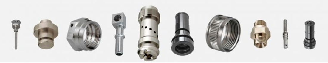
Multi-Spindle Machining is used for the mass production of “primarily turned” parts with some milled features, like those shown below. Instead of a single spindle, these machines contain multiple spindles and produce multiple parts in parallel. At each spindle there may be end slides and/or OD slides (also known as cross slides) with live tooling capabilities. The workpiece is indexed through each of the spindles in sequence, with different features machined at each index position. By the time the workpiece has indexed through all the spindles, the part is complete.
Multi-Spindle Machining involves level loading the features made and operations performed at each spindle, in order to minimize the overall part cycle time. That is, the goal is to distribute the various operations across the spindles so that the elapsed machining time at each spindle is as equal as possible. This can include performing multiple operations simultaneously on a single workpiece at a single spindle, using end slides and OD slides.
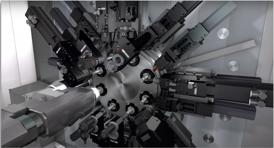
The picture below shows a sophisticated 8-spindle machine which machines 8 parts in parallel.
Supported machine types:
There are many variants of Multi-Spindle machines. The aPriori Multi-Spindle Machining cost model supports only the following types of machines:
-
CNC Multi-Spindle machines
-
CNC Turning Center machines.
The following machine types are NOT represented by the cost model at this time:
-
CAM Multi-Spindle machines (including use of Form tools)
-
Rotary Transfer machines
-
Swiss-Lathe machines
-
Any type of simultaneous MILLING machines
Supported part sizes and stock forms
Multi-spindle machining typically is used for small-to-medium sized parts. Outer diameters of 2 inches or less are typical but some machines can accommodate parts of up to about 8 inches. aPriori's Regional Data Libraries 2022-07 currently include machines which can accommodate stock diameters up to 90 inches (~ 3.5 inches).
The aPriori Multi-Spindle Machining cost model supports parts made from standard Round Bar, Round Tube, Hex Bar, and Square Bar stock. It does NOT support estimating secondary machining of parts made from a net-shape process such as casting or forging.
Innovations in the Multi-Spindle Machining cost model
The Multi-Spindle Machining cost model leverages many aspects of the Stock Machining cost model but includes a number of additional capabilities to enable the "level loading" of operations across spindles and slides. These advances are:
-
Determine Spatial Relationships between GCDs and Order of Operations based on GCD Accessibility
For Multi-Spindle Machining, it is necessary to determine the order in which features can be machined in order to distribute them among the available spindles and slides in a plausible way. Any material removal operation needed to expose/access a feature (GCD) must occur before the operation which machines that feature, when we are determining our level-loading strategy.
The Geometry Analysis engine now provides Lies Above relations which characterize how features are spatially related . The Cost Model logic uses these relationships, or knowledge of the spatial ordering of features, to constrain how and when features and operations can be assigned to the available spindles.
This figure of a part made from round bar stock illustrates the level loading concept and lies above relations.
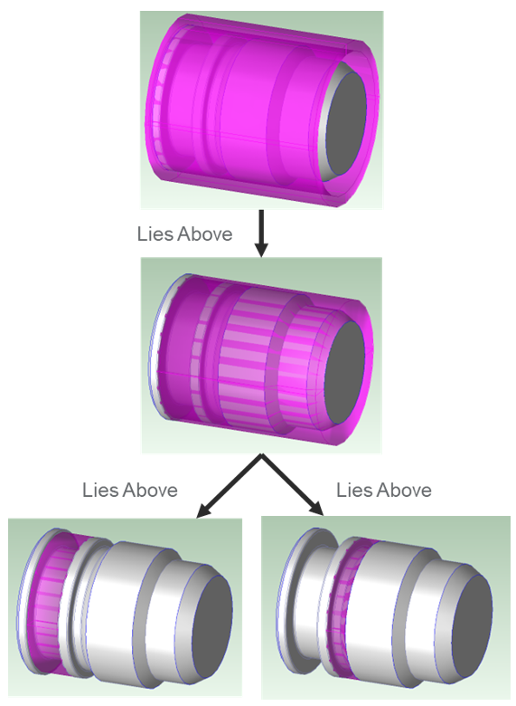
The top image shows that there is some stock allowance or extra margin around the OD.
That OD margin needs to be machined away, to expose a second Ring of material which extends almost the entire axial length of the part. This second Ring GCD is displayed in the middle picture.
Once that second Ring of material is machined away, we can access smaller Rings of material to be removed, with smaller ODs and axial extent, as shown in the bottom images.
-
Simultaneous Operation Feasibility Assessment
The Multi-Spindle Machining model determines whether two operations can be performed simultaneously, using the slides available at the spindle. For example, it is not feasible to drill a hole through the side of the part, which requires the part to be stationary, rough turning some material from the part OD, since those operations require the part to be rotating.
-
Load-Balancing Logic
The Multi-Spindle Machining model includes a basic load-balancing algorithm for assigning features and operations to the various spindles and tools available at each spindle, in order to minimize total part cycle time. The algorithm uses a proprietary weighting system which considers the interdependency of operations to place key operations on earlier spindles and then assign the remaining operations in a physically logical order. Note that aPriori's algorithm is a single-pass algorithm; it does NOT iterate or evaluate alternate possible arrangements of the operations. However, this algorithm is fast and produces acceptable results, as confirmed by external subject matter experts, on a test set of parts received from a good spectrum of customers.
-
Simultaneous Operation Viewer
The Multi-Spindle Machining process group includes a new dialog, the Simultaneous Operation Viewer , which provides a graphical display of the available spindles and slides and the features and operations assigned to each of these. This enables the user to easily assess when and where various operations are occurring.
For example, this part has been evaluated and assigned to a CNC Multi-Spindle class machine with 6 spindles.
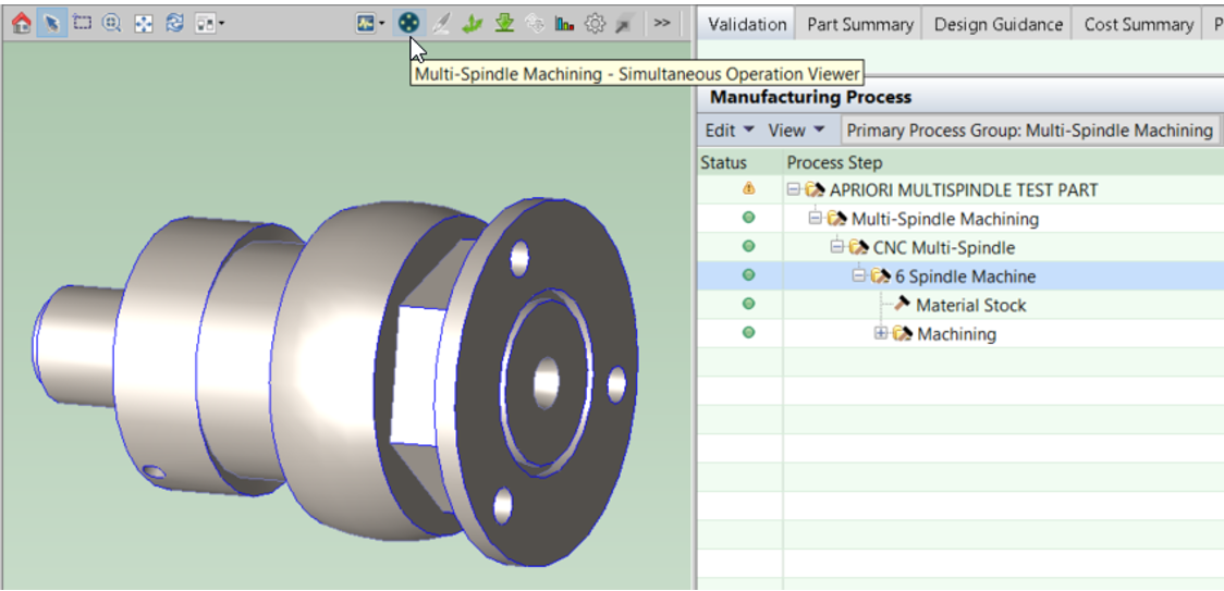
If you click on the Simultaneous Operation Viewer button in the aPriori Professional toolbar as shown in the previous figure, the dialog in this figure appears.
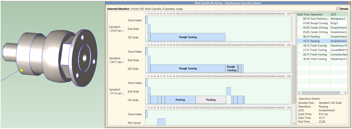
There is a green row for each Spindle. For each green row, there are multiple blue rows depicting the operations occurring on the tooling available at each spindle. These blue rows function like a Gannt Chart, showing the sequencing and duration of operations. You can click on an element within each blue row, such as the Pecking operation in the picture above. Selecting an element highlights the relevant GCD in the Viewer and also in the Details pane at the right of the dialog. This Details pane displays a sequential list of all operations occurring on a given tool/slide at a given spindle. The Details View makes it easier to review operations which are very short in duration and may be hard to distinguish in the Gannt-style view. Selecting a row in the Details pane also highlights the relevant GCD in the Viewer and in the Gannt-style view.
-
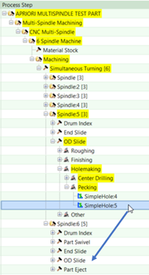
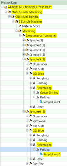
Reassigning Operations
If desired, you can adjust how aPriori assigned operations to the available spindles and slides. In the example above, SimpleHole:5 is created by Drilling and Pecking operations which occur on the OD slide of Spindle 5. If you wish to reassign this operation to the OD slide of Spindle 6, you can do this by dragging and dropping the GCD operation in the Manufacturing Process pane as shown in this example:
-
Click on SimpleHole:5 under Pecking operation, hold down left mouse button and drag to OD Slide of Spindle 6.
-
SimpleHole:5 Pecking operation now will appear under Spindle 6.
-
You must re-cost the part to recalculate cycle time impact.
Note: You cannot drag and drop operations in the Simultaneous Operations Viewer.
Note: If you reassign operations to a different slide or spindle, aPriori does not prevent invalid assignments. For example, a user could assign the Pecking operation to an earlier spindle instead of a later one, even if the pre-requisite Center Drilling operation remains on the original spindle. Similarly, a user could reassign an operation that requires an End Slide to an OD slide; aPriori will not prevent or warn about this. It is the responsibility of the user to ensure that any manually-assigned operation placements are valid.
Note: By default, only the operation that is manually reassigned is moved to a new spindle or tool. However, if you wish to have aPriori automatically reassign operations that are dependent on the manually-reassigned operation (i.e. must occur after it), set the process setup option Method Used to Rebalance Operations After Override to Rebalance Operations After Override and re-cost the part. The dependent operations will be re-assigned so that they are sequenced correctly after the original re-assigned operation. It is possible this may result in a failed costing, if there are not sufficient remaining spindles or tools to accommodate re-sequencing the dependent operations.
-
Limitations for the Multi-Spindle Machine Cost Model
-
No Support for Form Tools and CAM Multi-Spindle Machines
Form Tools are custom-designed tools with a cutting profile in the inverse shape of the geometry to be turned. These are moved (plunged) into the workpiece in the axial direction. Typically these are designed to machine some length of the turning profile simultaneously, thereby reducing cycle time compare to single-point turning operations. aPriori does not determine which GCDs could potentially be machined with a common Form Tool, so assumes only single-point turning. CAM Multi-Spindle machines frequently rely on the use of Form tools because these machines cannot move radially and axially simultaneously. Therefore CAM Multi-Spindle machines also are not supported.
-
Slide Configuration is Manually Specified not Automatically Optimized
aPriori does not determine an optimal configuration of OD Slides and End Slides for making a given part; instead machines with different slide configurations are defined in the Digital Factor and aPriori evaluates the part with respect to those machine configurations.
-
No Support for "Double Drop" machine configurations
aPriori assumes that all available spindles are used to make the features of a single part. There is no support for "double drop" capabilities, for example configuring an 8-spindle machines to behave as two 4-spindle machines in which a single workpiece is processed on only 4 of the spindles.
-
Limited Design Guidance
The Multi-Spindle Machining process group does not currently flag Design for Manufacturability or Design to Cost issues. This capability may be added in a future release based on customer demand.
Improved Load Balancing and Cycle Time Estimates
Achieve more comparable machining times at each spindle and lower overall part cycle time estimates.
aPriori Professional 2022 R1 SP1 achieves more comparable machining times at each spindle and lowers overall part cycle time estimates by distributing certain operations with long cycle times across multiple spindles.
Previously, aPriori assumed a single rough turning operation performed on a single GCD must occur entirely on a single spindle. For parts which include individual GCDs with relatively high cycle-times, this prevented a roughly even distribution of operations and cycle times across spindles. Instead, one spindle would have a substantially longer cycle time than others, resulting in an over-estimate of part cycle time. For example, consider a part with a sizeable hole that runs the entirety of its length. The cycle time to drill that hole may be significantly longer than that of any other operation on the part, and would drive elevated part cycle times if performed entirely on one spindle. To mitigate this issue, aPriori now automatically will split some types of operations into multiple distinct operations which can be assigned to different spindles in order to balance cycle time. The details of this are explained below:
-
Operations which may be split across multiple spindles include Pecking and Drilling of SimpleHole GCDs and Rough Turning of Ring GCDs
-
aPriori provides Digital Factory Managers with some flexibility to control when and how an operation is split across multiple spindles. By default, the following criteria is applied:
-
SimpleHole GCDs may be split if their overall length is greater than or equal to 80% of the total length of the part.
-
Ring GCDs may be split if their volume is greater than or equal to 22% of the total volume removed from a part.
These size-based thresholds are configurable and are accessed in a lookup table
tblMultiSpindleOpSplittingThresholds. This table also includes a field to disable operation splitting if desired (retaining the behavior of the previous release). -
Digital Factory Managers also can control the degree to which an operation may be sub-divided across spindles, depending on the number of spindles available on a given machine. For example, you may allow a hole drilling operation to be divided across up to 3 spindles on an 8-spindle machine, but only 2 spindles on a 6-spindle machine. These behaviors are specified in a lookup table tblMultiSpindleOpSplitting. This is the default behavior:
-
Rough Turning of a large-volume Ring GCD may be split across 2 spindles on a 6-spindle machine and 3 spindles on an 8-spindle machine
-
Drilling of a long SimpleHole GCD may be split across 3 spindles on both 6-spindle and 8-spindle machines
-
Pecking of a long SimpleHole GCD may be split across 3 spindles on both 6-spindle and 8-spindle machines
-
Operations are not split on 2-spindle machines
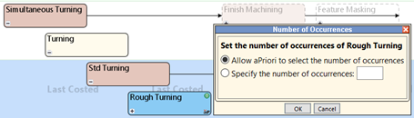
Users also can manually distribute an operation across multiple spindles. To do this, open the Operation Sequence Selection dialog for the given GCD, right-click on the operation and select Number of Occurrences as shown in this figure.
Due to these Load Balancing improvements, cycle time estimates will decrease for parts containing the long cycle-time GCDs described above, compared to the previous release of aPriori. The amount of decrease will depend on the specific feature geometry and the number of spindles on the selected machine. In a set of test parts, over 70% had GCDs that now are subdivided between multiple spindles. Cycle time decreases ranged between 25% up to 44% for these test parts, with the largest decreases observed on 8 spindle machines.
Multi-Spindle Machining Enhancements Based on Early Visibility Feedback
Take advantage of additional improvements to the Multi-Spindle Machining model, based on feedback from "Early Visibility" program participants.
aPriori Professional 2022 R1 SP1 includes these additional improvements to the Multi-Spindle Machining model, based on feedback from Early Visibility program participants.
Reduced Number of Operators and Labor Cost Estimates
The number of operators has been updated for CNC Multi-Spindle and CNC Turning Center machines to reflect the high level of automation assumed for this process. Previously aPriori assumed one operator per machine by default. This now is updated to 0.25 operators (1 operator per 4 machines) for 6 and 8 spindle machines, and to 0.5 operators (1 operator per 2 machines) for 2 spindle machines. As a result, Labor Costs will decrease by 75% and 50% respectively, compared to the previous “early-adopter” release of the Multi-Spindle Machining cost model. As Multi-Spindle Machining a highly automated process, the effect on Fully Burdened Cost is much lower, with a reduction in the range of 5-10%.
Updated Part Size Limits for Large Virtual CNC Multi-Spindle Machines
The Large size virtual CNC Multi-Spindle machines in the aPriori RDLs were updated to reflect the fact that this class of machines can make somewhat larger parts than previously reflected.
The maximum part length limit for the Large Virtual 6 and 8 Multi-Spindle machines has been increased to 205 mm (about 8 inches) from the previous value of 120mm (4.72 inches.
The maximum workpiece diameter limit for the Large Virtual 6 and 8 Multi-Spindle machines has been increased to 90 mm (about 3.5 inches) from the previous value of 50 mm (about 2 inches).
As a result, these machines now may be selected for some parts which previously were assigned a Virtual CNC Turning Center machine. Labor and Overhead Costs may change as a result.
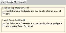
Scrap Buyback Options Now Available, Affecting Material Cost Estimates
The Multi-Spindle Machining process group now provides process setup options Enable Scrap Part Credit and Enable Scrap Material Credit. The options adjust Material Cost estimates by including the impact of selling scrapped parts and/or scrap material produced by the Multi-Spindle Machining process, respectively. Previously these options were available in Stock Machining and other process groups but not in the Multi-Spindle Machining process group. By default these options are not selected, so Material Cost estimates do not include the impact of scrap buyback. Selecting these options will lower Material Cost. The default behavior can be controlled by the cost model variables enableScrapMaterialCredit and enableScrapPartCredit.
Improved determination of simultaneous operation feasibility, based on spindle speed
aPriori's Multi-Spindle algorithms are now more restrictive when determining whether two operations, which both require the spindle to be turning, can be performed simultaneously at the same spindle. Previously aPriori allowed two operations with fairly disparate recommended spindle speeds to occur at the same time, on the same spindle. Now aPriori will not allow simultaneous operations if the spindle speed requirements for the operations differ by more than 10%. This is true for both automatically computed and user-specified spindle speed values. This default threshold can be altered by Digital Factory Managers via the cost model variable spindleRPMPercentageDifferenceLimit in the Machining Process Group.
Due to this change, part cycle times may increase compared to the previous release of Multi-Spindle Machining. This is because there are more constraints on which operations can occur simultaneously. In a set of test parts, cycle time increases were modest for the majority of parts; only 15% of parts had increases of more than 10% on 6-spindle and 8-spindle machines and 23% of parts had increases of more than 10% on 2-spindle machines. For the parts with larger increases, average increases were on the order of 25% or less, but in isolated cases larger increases were seen, especially for 2-spindle machines.
Display of Spindle Speed for Multi-Spindle Operations
Multi-spindle machining operations assigned to GCDs now provide an informational process setup option which displays the spindle speed required for the operation. Spindle speed already was displayed in the Stock Machining process group, so this enhancement just provides equivalent functionality for the Multi-Spindle machining process group.