Casting - Investment Enhancements
aPriori 2023 R1 provides a set of enhancements to the Casting-Investment process group. The Casting-Investment manufacturing process model was enhanced to improve the accuracy of cost estimates by accounting for the slurry and sand expendable tooling costs used to create the investment cast mold.
Slurry and Sand Cost for Investment Casting Estimates
The Investment Casting Shell Making manufacturing process model now includes the cost of the slurry and sand used to make the mold as Expendable Tooling costs.
As this figure shows, the Shell Making dialog contains new process setup options (PSOs) for configuring slurry and sand costs.
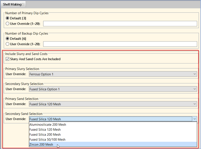
The new settings are:
-
Include Slurry and Sand Costs – Checkbox option to include the slurry and sand costs. This option is selected by default and is controlled by the
defaultIncludeSlurryAndSandCostscost model variable. -
These four drop down menus, which allow you to select the primary and secondary material compositions for both slurry and sand.
-
Primary Slurry Selection
-
Secondary Slurry Selection
-
Primary Sand Selection
-
Secondary Sand Selection
-
The estimated sand and slurry costs will vary based on both raw material cost of the primary and secondary compositions and the amount of sand and slurry needed to create the shell around the wax pattern tree.
The aPriori baseline Regional Data Libraries include supporting cost data for common types of sand and slurry binder and refractory materials. You can also add your own sand and slurry materials and costs for a specific process by using Toolshops and lookup tables in the Digital Factory Manager.
Read Draw Direction from CAD File
aPriori 2023 R1 provides a new capability to use a CAD-defined draw direction to reduce analysis times and support highly-automated aPriori workflows.
Historically, aPriori has relied mainly on its powerful, proprietary algorithm for analyzing the geometry of molded parts (including plastic injection moldings, castings, and forgings) and determining the draw direction (mold-opening direction). This algorithm evaluates many candidate directions and selects one based on many criteria including the amount of undercut volume, alignment with various features on the part, flatness of the resulting parting line and required mold-opening height. In some cases the draw direction ultimately selected by aPriori, while reasonable, is different than the intended as-designed draw direction. Therefore, aPriori has also allowed you to specify the desired Draw Direction interactively. To do so, you had to inspect and, as needed, edit the draw direction and then recost the component using newly extracted GCDs.
In this release, instead of using the proprietary algorithm, you can configure aPriori to read and use designated datum references in the CAD file as the specified Draw Direction. Doing so eliminates the need to manually review and sometimes update the chosen draw direction, and also results in faster GCD extraction. This capability is available in aPriori Professional (for both on-premise and cloud deployments) and Cost Insight Design, (for cloud deployments), and is particularly useful for supporting high-volume lights-out workflows, which leverage aPriori Generate.
These process groups support reading Draw Direction from NX, CATIA, SolidWorks and Creo CAD models (including both Creo Direct Integration and CAD-I/cloud environments):
To leverage this capability, your organization must:
-
Adopt some company-standard ways of designating draw direction in your CAD models.
-
Configure the CAD Property Mapping File to identify the standard draw direction references.
An aPriori System Administrator can perform this step.
If a newly costed CAD model contains your company-standard draw direction references, aPriori will use them. Otherwise, it will fall back to using the proprietary algorithm for determining draw direction.
Draw direction references are defined for the entire aPriori deployment. aPriori provides flexibility in how draw direction may be designated, to support different naming conventions, languages, and modeling approaches used within different divisions of a company or standards which have evolved over time.
Here is a summary of the rules for designating draw directions. For complete details, please refer to the Draw Direction Mapping section in version 2023 R1 of the aPriori Professional System Administration Guide.
In general, aPriori supports specifying draw directions using these types of CAD entities:
-
An axis of a coordinate system with a custom name (for example, the Z-axis of the coordinate system named "Draw_Direction")
-
A datum axis with a given name
-
A datum plane with a given name (draw direction is perpendicular to the plane)
aPriori allows you to define multiple possible draw direction references in the CAD Property Mapping File as well as a priority order. When analyzing a part file, aPriori uses the highest-priority reference that exists in that part file as the draw direction. To capture when the draw direction is read from the CAD file, these new properties are available for the Parting Line GCD:
-
Mapped Draw Direction Name displays the full name of the CAD datum object that defines Draw Direction. If this field is empty, then draw direction was not read from the CAD model and the historical algorithm was used.
-
Mapped Draw Direction Type displays the type of the CAD datum object that defines Draw Direction. Possible values are Coordinate System, Axis, or Plane.
-
Mapped Draw Direction Axis is used only if Mapped Draw Direction Type is equal to Coordinate system and if so displays the axis of that coordinate system used to define draw (X, Y, or Z) otherwise no value is displayed in this field.