Machining Enhancements
aPriori 2023 R1 provides these enhancements for processes in the Machining process group:
Grinding Enhancements
Several significant grinding processes enhancements enable aPriori 2023 R1 to:
-
Assign more realistic and appropriate grinding processes.
-
Provide more accurate estimates of grinding cycle times and costs for grinding processes that are needed to achieve specified tolerance or surface finish requirements.
-
Provide helpful Design for Manufacturability (DFM) guidance when a grinding process is determined to be infeasible due to part geometry.
More Automated and Accurate Estimates of Grinding Setup Times and Costs
aPriori now automatically estimates the setup time and cost required for grinding processes, by determining the number of distinct part setups required for the grinding tool to access the surfaces of interest.
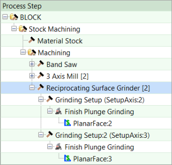
The manufacturing process pane now displays one or more grinding setup axes when a grinding process is assigned to a part. The number of setup axes is equal to the number of orientations that the part must be placed in to access each surface that requires grinding. The number of setups required for grinding and the corresponding time and cost is generated for these five processes:
-
Reciprocating Surface Grinder
-
Cylindrical Grinder
-
Internal Grinder
-
Rotary Surface Grinder
-
Jig Grind
For clarity, the existing gear grinding process setups (Profile Gear Grinding Setup and Threaded Wheel Gear Grinding Setup) have been renamed to Grinding Setup.
The type of setup axis selected by aPriori depends on the type of the part surface and grinding process applied to it. Reciprocating Surface Grinders and Rotary Surface Grinders are applied to flat (planar) surfaces and have a setup axis that points perpendicular and away from the surface, toward the direction from which the grinding wheel would approach the surface. Lathe-type processes, such as Cylindrical Grinders and Internal Grinders, grind cylindrical part surfaces while the part is turning about an axis, so a turning axis is selected for these processes.
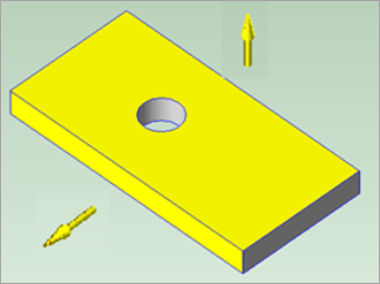
Consider the simple example part in this figure.
|
|
The top surface and one side wall (both shown in yellow) have a Roughness Ra requirement of 0.2 um. The part must be set up twice on a Reciprocating Surface Grinder machine so that each surface can be accessed by a grinding wheel that approaches from above.
Therefore, there are two Grinding Setups displayed in the manufacturing process pane. The orientation of the part for each setup is displayed as a yellow arrow in the Viewer window; the arrow points upwards away from the grinder table towards the grinding wheel.
The estimated part setup time is based on part mass and is specified in the lookup table tblHandlingTimes. The part setup time is a portion of the cycle time displayed for each Grinding Setup, which also includes actual grinding time.
For example, in this figure, the cycle time per Grinding Setup is 34 seconds, which includes 23 seconds of part setup and 11 seconds of grinding.
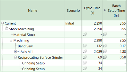
Part setup is distinct from Batch Setup Time, which is displayed in a separate column and is the time required to set the machine up for the entire batch of parts, amortized over the batch size.
By default, aPriori assumes that a part is set up only once in each orientation for grinding. You can specify if a Setup is repeated using the process setup option Repetitions of Part Setup, as well as override the computed Total Part Setup Time. These process setup options are available on each Grinding Setup, as shown in this figure.
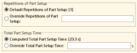
The new grinding setup analysis is more mechanistic and automated. The new setup options also enable more precise overrides for part setups.
Therefore, the new process setup options replace several process setup options that were available in previous releases of the Machining manufacturing process model. Specifically, these setup options are no longer available for Reciprocating Surface Grinder, Rotary Surface Grinder, Cylindrical Grinder, and Internal Grinder processes:
-
Number of Part Setups
-
First Part Setup Time
-
Subsequent Part Setup Time
Enhanced DFM Guidance for Surface Grinding Operations
aPriori now provides improved design for manufacture (DFM) guidance when a grinding operation cannot fully access a surface.
To explain why a given grinding process is not suitable for a part or specific part surface, aPriori2023 R1 includes multiple new or improved design for manufacture (DFM) guidance for Manufacturability Issues. The specific guidance that is presented depends on the type of surface and grinding process being evaluated.
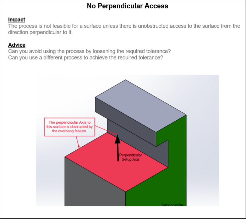
For example, the Reciprocating Surface Grinder and Rotary Surface Grinder processes, which are applied to flat (planar) surfaces, support Plunge Grinding operations. The Reciprocating Surface Grinding process can also support Traverse Grinding operations.
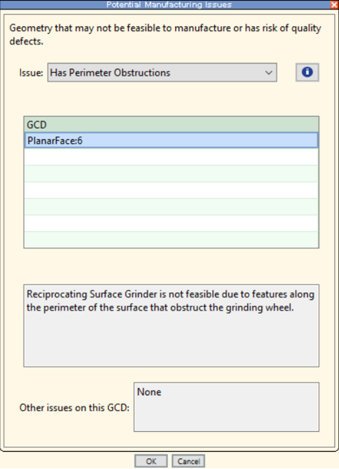
However, as this DFM guidance now clearly conveys, to enable the grinding wheel to approach the surface from above when the part is mounted on the machine table, both processes require full, unobstructed access to the surface in a direction perpendicular to the surface.
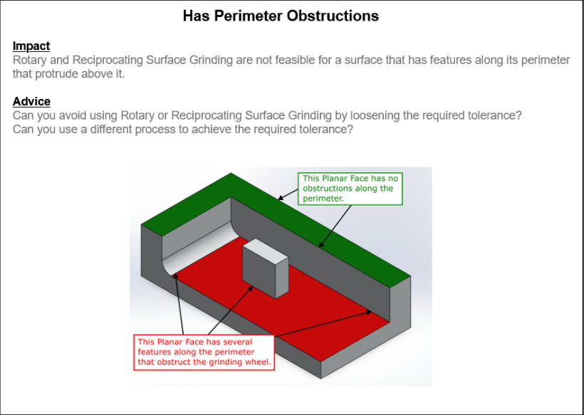
Furthermore, as this DFM guidance explains, the Reciprocating Surface Grinder and Rotary Surface Grinder processes cannot be used on surfaces that are interrupted or bordered by protruding features.
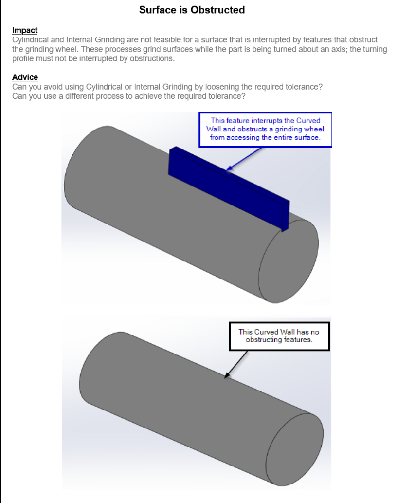
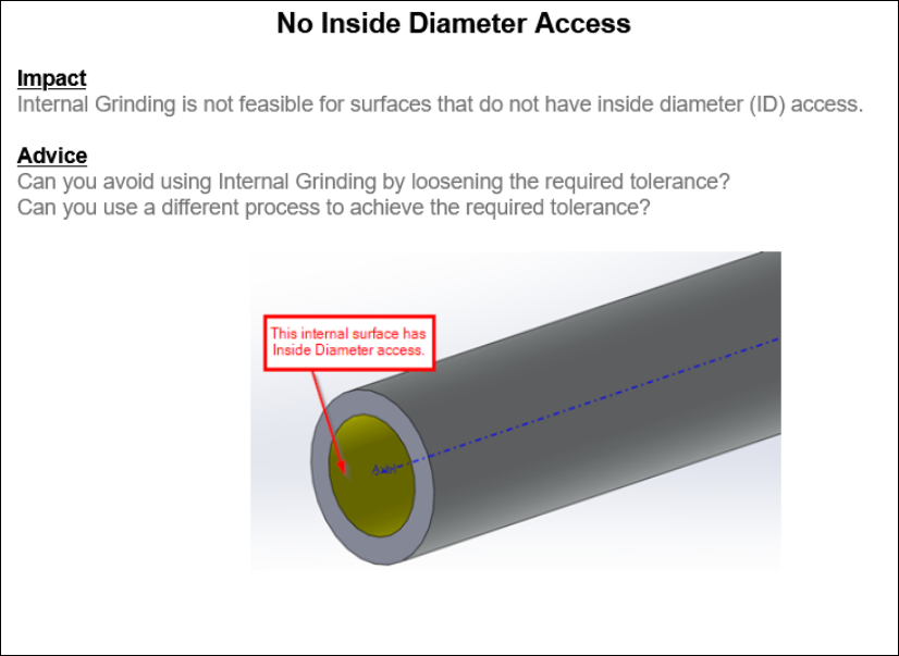
Cylindrical Grinding and Internal Grinding are lathe-type processes that grind surfaces while turning the part about an axis. Cylindrical Grinding is used to grind exterior surfaces of cylindrical parts. Internal Grinding is used to grind interior surfaces of holes and bores on parts. aPriori generates a setup for each distinct axis of rotation that is required for the process.
However, as these DFM guidance convey, such grinding processes are not feasible if:
-
Protruding features interrupt the surface.
-
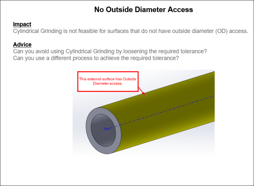
The surface is not accessible from the exterior direction (for Cylindrical Grinding).
-
The surface is not accessible from the interior direction (for Internal Grinding).
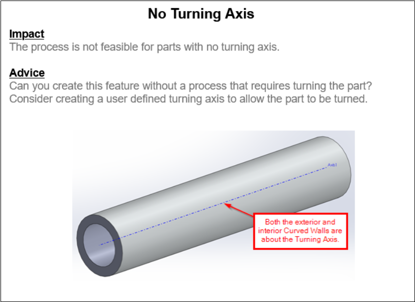
aPriori now displays this DFM guidance to indicate that it has not identified a turning axis on the part for a feature that requires a rotational grinding process. This situation can occur if a part is generally NOT rotationally symmetric and therefore would be challenging to mount securely and balance on a lathe-type machine. To enable aPriori to cost the feature, you can add your own turning axis with the Modify Turning Axes tool.
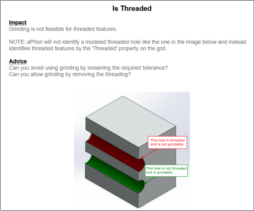
This final example shows the DFM guidance that aPriori Professional displays to warn that Grinding is being applied to Threaded holes. The Internal Grinder process currently assumes the use of straight / unprofiled grinding wheels, which damage threads.
General Grinding Operations No Longer Will Be Assigned
aPriori now evaluates alternate grinding processes instead of assigning a "General Grinding" operation as a placeholder.
Previously, each grinder process (Reciprocating Surface Grinder, Rotary Surface Grinder, Cylindrical Grinder, Internal Grinder, Jig Grind) included a fallback operation called "General Grinding" which could be assigned when realistic operations such as Plunge Grinding, Traverse Grinding, or Internal Grinding were determined to be infeasible. General Grinding operations were originally intended avoid costing failures by indicating that some secondary operation is required to achieve a tight tolerance or surface finish requirement and to account for the cost of that secondary operation. However, because the General Grinding operations did not have strict feasibility rules, aPriori could select an unrealistic Grinder process.
For example, a Cylindrical Grinder process could be selected for a flat planar surface. This occurred because the availability of a General Grinding operation prevented aPriori from continuing to evaluate other potentially applicable grinding processes. Additionally, the cycle time and cost estimates for these General Grinding operations often were not sufficiently accurate.
As of 2023 R1, General Grinding operations have been removed from the Grinder manufacturing process models. aPriori now will evaluate only the “real” discrete mechanistic grinding operations available in the various Grinder processes. As a result of this change, compared to the previous release of the machining process model, a different grinding process and operation can now be assigned to a surface with a tight tolerance or surface finish. If no realistic grinding operation is found to be feasible for the surface, the surface GCD might fail to cost entirely.
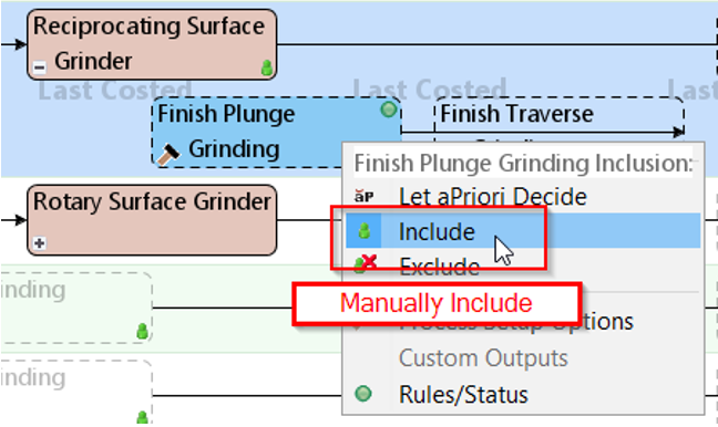
If the selected Grinding operations fail, aPriori displays Design Guidance that communicates the failure. If you think that aPriori has been too restrictive in its selection to get an estimate, you can override feasibility rules. You might have to manually include the grinding operation and override the feasibility rules at a specific, lower-level operation sequence, rather than at a higher-level routing alternative.
For example, a PlanarFace GCD can fail a feasibility check due to lack of an accessible Grinding Setup if it is assigned the Side Milling operation before a tolerance is applied.
For this type of issue, follow these steps:
-
Disable the feasibility rule check for the Grinding process directly where it appears after the Side Milling operation.
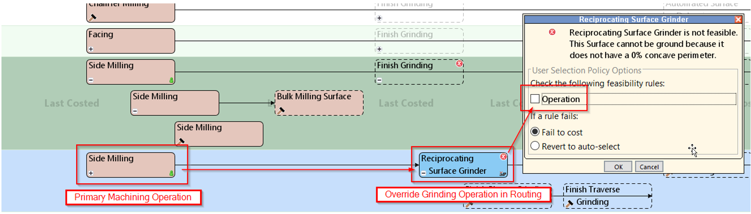
-
Manually include the Grinding process as a separate operation.
Updated Plunge Grinding Cycle Time Estimates
aPriori now accounts for grinding wheel alignment time in Plunge Grinding cycle time estimates.
A Plunge Grinding operation requires the part to be aligned with the grinding wheel at a specific location. The grinding wheel then plunges into the part while it remains in the set location. The operation cycle time now includes both the time required to align the wheel with the surface GCD and the grinding time.
The required Alignment Time is now specified as a machine field. This value is set to 2 seconds for machines that have an automated alignment capability, and 10 seconds for those that do not.
This table outlines the Process, GCD, and Operation routings for which alignment time is included.
| Process | GCD | Operation |
|---|---|---|
| Cylindrical Grinder | Curved Wall | OD Finish Plunge Grinding |
| Internal Grinder | Simple Hole | ID Finish Plunge Grinding |
| Internal Grinder | Curved Wall | ID Finish Plunge Grinding |
| Jig Grind | Simple Hole | ID Finish Plunge Grinding |
Impact Analysis for Grinding Enhancements
-
aPriori may select a different grinding process than it previously selected.
-
A GCD may fail to cost if no Grinding operation is considered feasible due to accessibility considerations. You can override the feasibility rule if you think that aPriori is being too restrictive.
-
Cycle time estimates may decrease because aPriori will no longer assign the General Grinding fallback operation, which tended to have overly high cycle times.
-
For heavier parts, cycle time estimates may increase due to the more mechanistic estimation of grinding setups
Tool Reach and Length-to-Diameter Improvements
-
More Accurate Milling Cycle Time Estimates and Design Guidance for Long Tool Reaches
-
Impact Analysis for Tool Reach and Length-to-Diameter Improvements
More Accurate Milling Cycle Time Estimates and Design Guidance for Long Tool Reaches
The Machining manufacturing process model now better identifies and more accurately computes cycle times for milling operations that require long tool reaches. aPriori also provides DFM guidance to flag geometry that requires long tool reaches, prompting design engineers to consider redesigning the part to reduce machining time and cost.
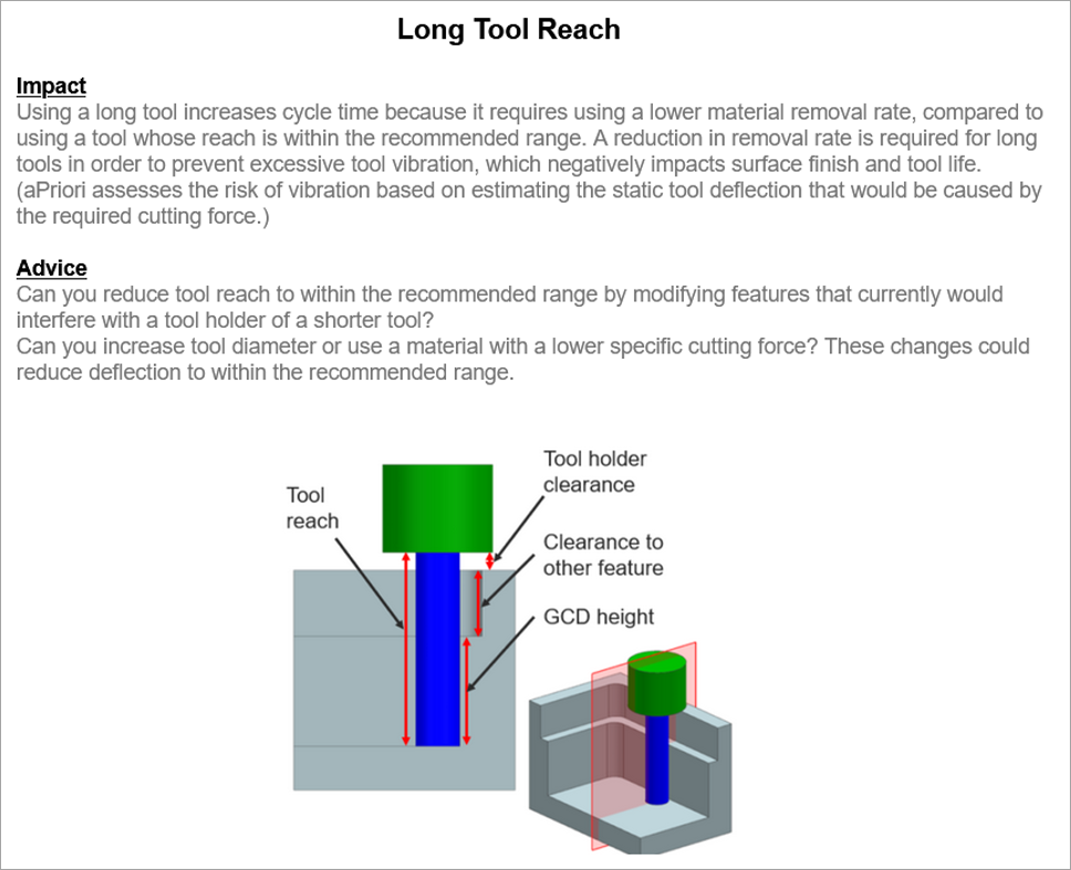
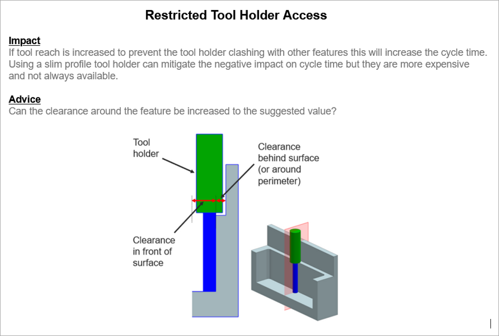
Tool reach is the length the tool must protrude from its holder to access the feature to be machined. As the tool reach increases, the setup becomes less rigid and the tool deflects more when it is subjected to machining forces. If not accounted for, the deflection can induce chatter vibrations and cause issues for achieving dimensional accuracy and finishing surfaces.
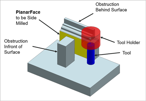
In previous releases, aPriori determined how far a tool must reach to mill a feature based only the length, along the axis of the tool, of the GCD to be machined. Now, aPriori also considers the clearance required to clear any nearby features that would otherwise obstruct the tool or the tool holder when determining tool reach.
As this illustration shows, when machining a GCD such as the wall (yellow), aPriori now checks if the tool holder (red) would be obstructed by features that are either in front of or behind the GCD. If an obstruction would occur, aPriori increases the length (reach) of the tool (blue) to eliminate the interference.
Additionally, aPriori now sets cutting parameters more appropriately. To do this, aPriori predicts the tool deflection for a given milling operation by using a static deflection model of the tool that depends on tool reach, tool diameter, tool material, machine power, and spindle speed. For more information, see the Cost Model Guide.
If the calculated deflection exceeds an allowable limit, aPriori compensates by reducing the cutting parameters. The allowable limit and affected parameters depend on the type of operation:
-
Roughing operations – The allowable limit is 150μm, above which the feed rate will be adjusted.
-
Finishing operations – The allowable limit is 25μm, above which the feed rate and axial cut depth will be adjusted.
The allowable limits can be adjusted by Digital Factory Managers via the cost model variables plant.toolDeflectionLimitFinishing and plant.toolDeflectionLimitRoughing respectively.
The default allowable limits are based on published deflection guidelines as specified by established machine tooling suppliers such as Sandvik Manufacturing Solutions.
To determine the tool reach required for a given milling operation on a given feature, aPriori considers the use of both standard types of tool holders (such as collet-type) and slim-profile extended-reach tool holders (such as extended reach shrink-fit type). Standard-type tool holders are preferred because slim profile tool holders are more expensive and not always available for all tool sizes. If the tool reach has to be increased to avoid interference when using a standard tool holder but the calculated tool deflection does not exceed recommended limits, aPriori assumes the use of a standard tool holder with that increased tool reach. Otherwise aPriori determines if the tool reach and tool deflection can be reduced to acceptable levels by using a slim-profile tool holder.
aPriori now provides new Design for Manufacturability and Design for Cost guidance for GCDs and milling operations that are affected by long tool reach concerns:
-
Long Tool Reach – aPriori displays this guidance, which warns that for a given GCD and milling operation, a long tool reach required machining cutting settings to be reduced and machining cycle time to increase, and suggests possible corrective actions.
-
Restricted Tool Holder Access – aPriori displays this guidance, which indicates that a slim profile tool holder is required to prevent interference with other geometry and an unacceptable amount of tool deflection.
When aPriori reviews the Restricted Tool Holder Access issues, it highlights both the GCD being machined AND the surface of the part that would interfere with a standard toolholder if tool reach was not increased. However, in aP Design (also known as Cost Insight Design), the surface that causes the interference condition is not highlighted.
Limitations
-
The Tool Reach enhancements described in this section apply only to these types of milling operations and GCDs:
-
Side Milling of PlanarFaces, and CurvedWalls
-
Rough Milling of Pockets, Slots, and SimpleHoles
-
Slot Milling of Slots
-
Perimeter Milling of Perimeters
-
-
Tool Reach is not yet considered for:
-
Rough Milling of Bulk Removal or Stock Trim GCDs
-
Facing or Contour Milling finishing operations
-
You can choose whether tool reach compensation logic is applied at the Digital Factory level, on a per-scenario basis, or both. At the:
-
Digital Factory level – The behavior is controlled by the boolean cost model variable, defaultToolDeflectionAndHolderClearanceOverride. When this variable is set to:
-
True - The tool reach compensation is enabled. That is, the cutting parameters will be adjusted if the potential deflection exceeds the allowable limit. This is the default value.
-
False - The tool reach compensation is disabled. That is, the cutting parameters will not be adjusted even if the potential deflection exceeds the allowable limit.
-
-
Scenario level – By default, the behavior is controlled by the tool reach compensation setting for the selected Digital Factory, but the default behavior can be overriden by the Tool Deflection And Tool Holder Clearance Override PSO on the Machining node.
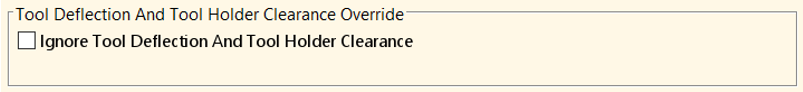
When the Ignore Tool Deflection and Tool Holder Clearance checkbox is:
-
Selected – The tool reach compensation behavior is disabled, regardless of the tool reach compensation setting for the selected Digital Factory.
-
Cleared – The tool reach compensation behavior is controlled by tool reach compensation setting for the selected Digital Factory.
-
Limitations
-
Angled walls may not generate a Design Guidance warning.
-
aPriori identifies only the nearest local obstruction for a feature. There may be other obstructions that also cause tool holder interference, however, to avoid long GCD extraction times aPriori does not search for additional obstructions.
Updated Feasibility Rules and Increased Allowable Tool Length-to-Diameter Ratio for Side Milling Operations
In the baseline machining process model, the maximum length-to-diameter ratio (L:D) in the determination of feasibility for Side Milling operations has been increased from 8 to 12, allowing for the use of relatively longer and skinnier tools, which generally require lower material removal rates.
The length-to-diameter ratio (L:D) limit for side milling, as controlled by the manufacturing process model variable difficultL2DRatio, is now set to 12 in the baseline machining process model. This adjustment was made in concert with the Long Tool Reach enhancements also introduced this release. For more information see, More Accurate Milling Cycle Time Estimates and Design Guidance for Long Tool Reaches.
Due to this enhancement, a GCD now may be assigned a side milling operation that was considered infeasible and therefore not assigned in a previous release. However, for side milling operations, material removal rates are lower and cycle times are higher when very high L:D tools are used instead of lower L:D ratios.
Impact Analysis for Tool Reach and Length-to-Diameter Improvements
As a result of the Tool Reach and length-to-diameter Improvements, milling cycle time estimates generally may increase compared to the previous release of the aPriori machining process model. The amount of change depends greatly on specific part features and whether long tool reach conditions are present.
Parts with deep and narrow pocket or slots, and parts with features located very close to walls are most likely to be affected by these changes. In a large set of test parts, 61% of the parts changed; of these 89% increased in milling cycle time and cost estimates. However, of these the average cycle time increase was only 4% and the average increase in fully-burdened cost was only 2%. The maximum increase in FBC observed was 17%, on a part with several deep recessed features.
If a different finish-milling operation now is assigned to a surface as a result of tool reach considerations and updated feasibility rules, the estimated milling cycle time may decrease for a specific part. For example, Facing may now be assigned instead of Side Milling. A small percentage of parts tested had a decrease in estimated milling cycle time; all decreased by less than 1%.