aPriori 2023 R1 provides a major revision of the Sheet Plastic processing group that includes new thermoforming machines, set-up options, and materials.
Overhaul for the Sheet Plastic Process Group
aPriori 2023 features a significant revamp of the Sheet Plastic process group to make the thermoforming manufacturing process model more mechanistic and accurate, resolve previous limitations, and improve usability. This enhancement includes improved geometry analysis, more intuitive inputs for stock size and part nesting, updated material cost calculations, additional materials and machine types, a mechanistic tooling model, and more automated comparisons of alternative routings and machine types.
Thermoforming is a plastic molding manufacturing process that utilizes heating of plastic sheet stock to a pliable form which is then molded to a die tool using a vacuum or vacuum & pressure. Any excess stock and required cut-outs are then trimmed using a CNC router.
Thermoforming is typically used for mid to low production volume parts and has the following benefits:
-
Cost effective at low volumes compared to injection molding due to significantly cheaper tooling
-
Typically fast lead times to production readiness
-
Excellent reproducibility
-
Lightweight, corrosion resistant alternative to some sheet metal parts
-
Supports complex shapes and deep draws
-
Can produce large parts due to the lower pressure required, compared to injection molding
-
Wide range of sheet plastic materials available to fulfill a wide range of required design, aesthetic and mechanical properties
Example parts from different industrial sectors include:
-
Agriculture: Vehicle panels, bulk containers, irrigation systems.
-
Automotive: Dashboards, instrument panels, truck beds, bumper covers.
-
Construction: Heavy equipment panels, sky lights, cladding, building panels, skirting.
-
Medical: Electronic equipment enclosures, PPE, equipment trays.
-
Consumer durables: Suitcases, cutlery trays, home appliances, toys.
General Process
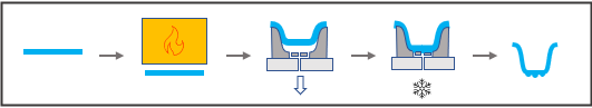
The general process for thermoforming is:
-
A plastic sheet stock of appropriate size and thickness is loaded into a thermoforming machine.
-
The sheet is positioned under an infrared heater until its temperature is high enough to form it.
-
The sheet is moved to a forming station and a vacuum is applied through the mold tool. Depending on the given form shape and plastic material, a pressure box, side actions and/or plug assist tooling also may be used to help shape the plastic.
-
The formed plastic cools.
-
The formed sheet is unloaded from the thermoforming machine.
After the formed sheet is removed from the thermoforming machine, it is loaded into a trimming station where a CNC router is used to trim the excess sheet stock and any holes or cut-outs to obtain the finished part.
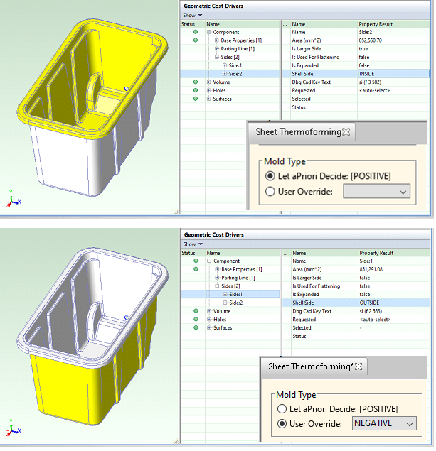
In contrast to other plastic molding processes, sheet thermoforming typically uses a tool that only contacts one side of the part. Tools, or molds, are identified as either positive (male) or negative (female) tools. Positive tools have a convex shape and therefore contact the inside surface of the finished part. Negative tools have a concave shape and contact the outside surface of the finished part. The choice of tool type depends, amongst other factors, on the shape of the part to be formed and the surface finish requirements. By default, aPriori assumes the use of a positive mold (controlled by the cost model variable moldType). Users can specify the desired tool type with the process setup option Mold Type.
aPriori uses the selected mold type and the Side GCDs to identify which side of the part is the tool facing side. If the mold type is positive, the Side GCD with the property Shell Side set to INSIDE will be defined as the tool facing side. For negative molds, the Side GCD with the Shell Side property set to OUTSIDE will be the tool facing side. This figure show the difference between the mold types and the tool facing sides as identified by aPriori.
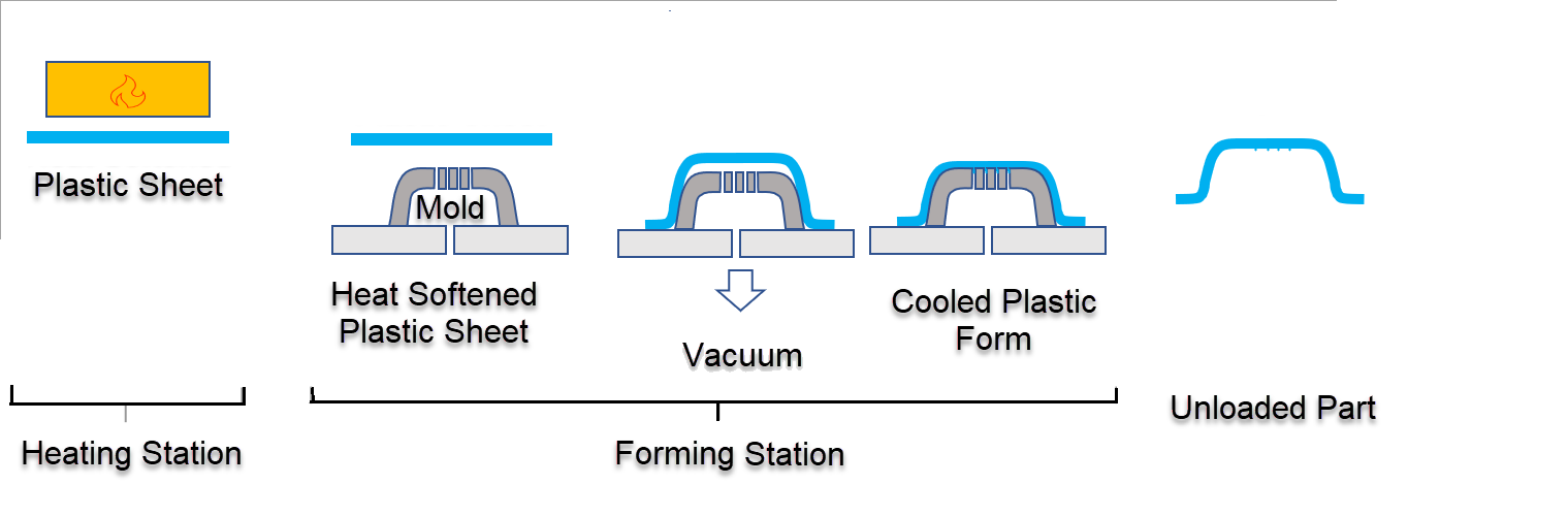
This diagram shows the thermoforming process when using a positive tool. The inside of the part is in contact with the tool (that is, the inside of the part is tool-facing).
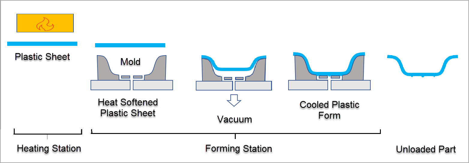
This diagram shows a thermoforming process that uses a negative tool. In this case, the outside of the part contacts the tool, and the sheet is pulled into the mold cavity rather than being pulled over it.
For more information about other tooling variants, including the use of pressure boxes and plug-assist mechanisms, see the 2023 R1 version of the aPriori Cost Model Guide.
Machine Types
Some thermoforming machines can process only one sheet of plastic at a time. Others can process multiple sheets simultaneously. The number of sheets that a thermoforming machine can process at the same time depends on the configuration of the tool. aPriori provides four different thermoforming tool configurations:
-
Single Station – The sheet is loaded and is transferred between the stations in series as it is heated, formed, and cooled. This machine configuration can only process one sheet at a time. This diagram shows a single station thermoforming machine configuration layout.
-
Shuttle Station – A single oven (heating) station is located between two forming stations. This configuration, which is also referred to as a Double Ender, allows the heating of one sheet to occur in parallel with the loading, forming, cooling, and unloading of the previous sheet. This machine configuration requires at least two tools that can process multiple sheets in parallel. This diagram shows a shuttle station thermoforming machine configuration layout.
-
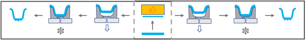
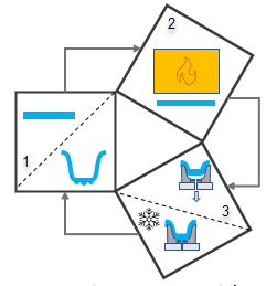
3 Station Rotary – Sheet material is loaded in station 1, rotated to station 2 where it is heated, rotated to station 3 where it is formed and cooled, and then rotated back to station 1 for unloading. This diagram shows a 3-station rotary thermoforming machine configuration layout.
-
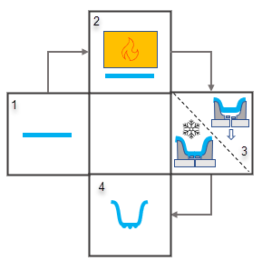
4 Station Rotary – Sheet material is loaded in station 1, rotated to station 2 where it is heated, rotated to station 3 where it is formed and cooled, and then rotated to station 4 for unloading. This diagram shows a 4-station rotary thermoforming machine configuration layout.
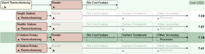
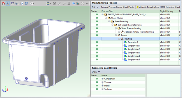
aPriori provides a distinct routing option for each machine type. By default, aPriori analyzes all four routings and selects the one with the lowest total cost. This diagram shows Sheet Plastic thermoforming routing options.
Cycle Times
The estimated process time and cycle time vary depending on the chosen process routing. This variation is due to different machine configurations enabling various activities to be performed in parallel. In aPriori Professional these activities are grouped into stages (multiple stages may be performed at the same station, as illustrated in the provided machine configuration diagrams).
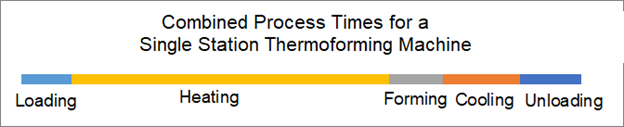
For a single station configuration, aPriori calculates the thermoforming machine process time as the sum of the time for each activity. Therefore, as this chart shows, the total process time for a single station thermoforming machine is the sum of the loading, heating, forming, cooling, and unloading process times.
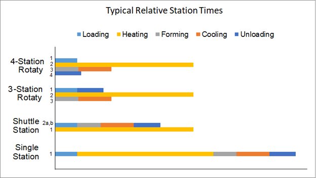
For multi-station configurations, aPriori calculates the thermoforming machine process time as the total time for the longest set of the parallel processes. For example, for a shuttle station the thermoforming machine process time is either the heating time or the sum of the loading, forming, cooling, and unloading times. Since the heating time is usually longer than the summed parallel process times for a multi-station configuration, the multi-station thermoforming machine process time is typically equivalent to the heating time.
This chart includes the four different machine configuration options and indicates the operations that occur in parallel for the multiple station configurations and the relative process times for the thermoforming machine configurations.
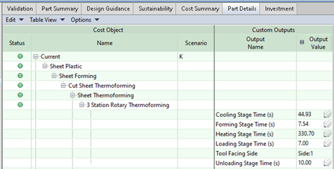
To examine the times for each stage, in the Parts tab, in the menu bar, click Table View and then select either All Data or Manufacturing Details. Next, expand the nodes in the Cost Object > Name column and the node in the Custom Outputs > Output Value column. As this figure shows, custom outputs for the selected thermoforming process shows the process time for each stage and indicates the Tool Facing Side), which is the side of the part that contacts the tool.
Labor Times
aPriori computes the labor time for loading the sheet into the machine, unloading the formed part, and supervising the machine as it heats, forms, and cools the sheet. The number of operators required for loading and unloading, which varies depending on the size and weight of the sheet, can be configured using the new lookup table componentLoadTime. The Number of Operators property for the selected machine represents the number of operators needed to supervise the machine while it heats, forms, and cools the sheet (that is, during the Non-Handling Stage Time ).
Stock Selection and Part Nesting
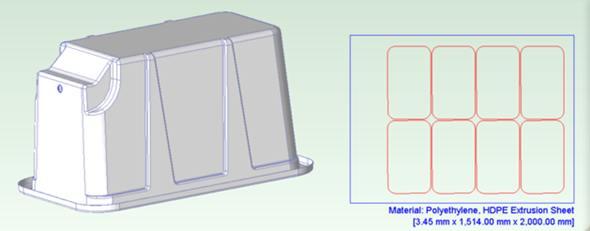
The new sheet plastic cost model enables users to view part nesting layouts. This functionality is controlled using the process setup option Number of Parts Per Sheet, which defines the number of parts to nest onto the sheet stock. aPriori nests the projected shadow of the part’s parting line in a rectangular pattern and considers inter-part spacing and clamping-related allowances to determine the required sheet size. The nesting layouts considered by aPriori are located in the lookup table layoutNumCav (starting point digital factories support between one to eight nested parts, with the default option of one part per sheet).
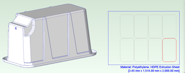
You can reconfigure the sheet dimensions by using the process setup options Minimum Sheet Length, Minimum Sheet Width, and Minimum Sheet Thickness. If you specify a sheet dimension that is larger than the size aPriori calculates is required for the specified number of parts, the nesting diagram will show any additional parts that can fit on the sheet in gray.
To optimize material utilization, instead of using standard stock items in baseline digital factories, aPriori defaults to using virtual stocks derived from the part dimensions, the nesting configuration, and the inter part spacing and clamping allowances. Digital Factory Managers can configure custom standard stock sizes in their digital factories. If they do so, aPriori will attempt to select a configured stock item before using a virtual stock if none are feasible. If aPriori finds multiple valid stock items, it selects the stock that results in the most cost-effective scenario.
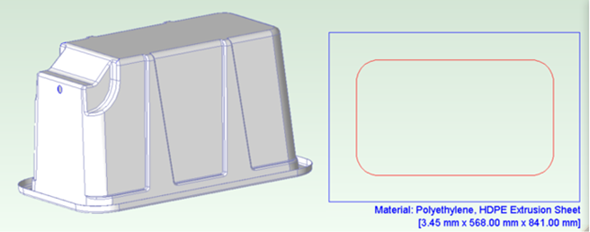
These figures show several different part nesting diagrams for the same part. The first figure shows the sheet size that aPriori calculated for a single part. The second figure shows the lager sheet that aPriori calculated to fit eight parts. The third figure shows the sheet size that a user specified for seven parts with an additional instance of the part (in a gray outline) that aPriori determined would fit on the specified sheet.
This table lists the materials that are available in the aPriori 2023 R1 baseline digital factories and indicates whether the material was available prior to this release or is new.
| Material | Available prior to 2023 R1 |
Introduced in 2023 R1 |
|---|---|---|
|
ABS, Extrusion Sheet GP |
Ö |
– |
|
ABS, Flame Ret |
– |
Ö |
|
ABS, PC-ABS |
– | Ö |
|
Acrylic PVC, PMMA PVC |
– | Ö |
|
Acrylic, PMMA |
Ö | – |
|
PET, CPET |
Ö | – |
|
Polycarbonate, Extrusion Sheet |
Ö | – |
|
Polyethylene, HDPE Extrusion Sheet |
Ö | – |
|
Polypropylene Random Copol |
– |
Ö |
|
Polypropylene, Extrusion Sheet |
Ö |
– |
|
Polypropylene, Impact Copolymer TPO |
Ö |
– |
|
Polystyrene HIPS Extrusion |
Ö |
– |
|
Polystyrene, G-P Crystal |
Ö |
– |
In previous releases, the material unit cost reflected the cost of purchasing resin pellets and converting them to sheet stock, rather than as-supplied sheet stock. Now all material costs are reflective of purchased plastic sheet stock. aPriori determines the required sheet thickness by using the finished part thickness (from the CAD model) and multiplying it by a stretch ratio to account for thinning of the sheet during forming.
Material Utilization and Material Cost
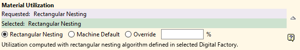
By default, aPriori calculates material utilization by dividing the total volume of finished parts nested on the stock sheet by the initial sheet stock volume. Users may instead choose to use the selected thermoforming machine’s Avg Utilization property or specify their own material utilization in the material selection dialog. This figure shows material utilization options, which are available in the Material Selection dialog. Note the nesting diagram is not supported for these utilization options.
Material Cost is calculated based on the unit cost of the selected stock. Although this release does not account for scrap buy back when calculation Material Cost, this capability is planned for a near-future release.
Router
A router process is applied to trim the perimeter of the part and cut any holes. Users can override the default feed rate of the router during the finish trimming process using the process setup option Router Feed Rate.
Tooling
In aPriori 23.1, the sheet thermoforming tooling model considers these major tool components and associated ancillary components:
-
Mold type (positive or negative)
-
Side actions (if applicable)
-
Pressure box (if applicable)
-
Plug (if applicable)
The cost to manufacture, assemble, and inspect the tool and individual tooling components is now calculated in a mechanistic model that considers these factors:
-
Design cost
-
Programming cost
-
Raw material cost
-
Purchased item cost
-
Labor costs including:
-
CNC machining
-
General machining
-
EDM machining
-
Water line drilling
-
Vacuum line machining
-
Finishing
-
Tool Assembly
-
Inspection
-
-
Miscellaneous services costs
-
Selling, general, and administrative costs
-
Mark-up costs
In a small set of test parts, the total capital investment costs for sheet thermoformed parts increased by 23% on average in aPriori Professional 2023 R1 versus prior results calculated in 2022 R1 SP1. Hard tooling cost may decrease in 2023 R1 for parts that have undercuts due to the bundling of undercut geometry to individual Core Pulls (see Undercuts and Side Actions).
Undercuts and Side Actions
aPriori extracts undercut features as Void GCDs. It then groups individual Void GCDs into a higher-level Core Bundle GCD that represents the voids that may be made with a common side action. For more information about how to control how Voids are grouped into Core Bundles, see the 2023 R1 version of the aPriori Cost Model Guide.
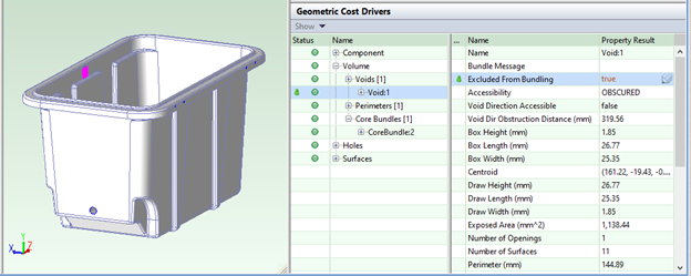
If an identified Void does not require a side action (for example, because the part is sufficiently flexible to remove it from the mold), you can set the GCD property Excluded From Bundling to true. Doing so ensures that the Void is neither included in a Core Bundle nor assigned a Core Pull operation.
This figure shows a Void that is excluded from being included in a Core Bundle.
All Voids that are not excluded from bundling will be grouped into a Core Bundle. Whether a given Core Bundle requires a side action to create the Voids contained within it will depend on whether it lies on the tool facing side of the part. If so, it will be assigned a Core Pull operation. Otherwise, it will be assigned an As Formed operation.
For example, the Core Bundle in this figure lies on the inside of the part.
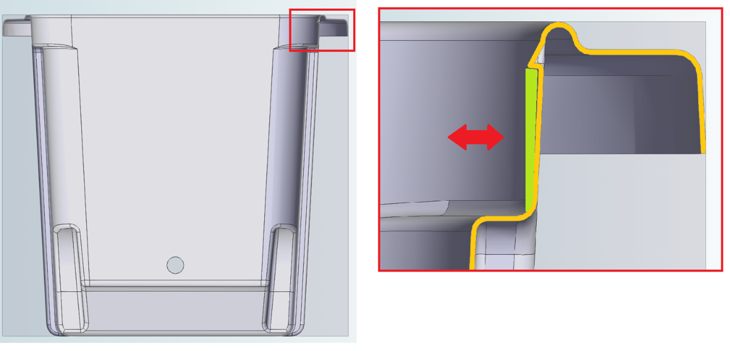
The undercut (in green) is represented by a Void contained within a Core Bundle. Since this part uses a positive tool, the inside of the part is tool facing, meaning that this undercut must be assigned a Core Pull operation.
The mold type is positive so this undercut lies on the tool facing side of the part and, therefore, requires side action tooling to create it. aPriori will assign this Core Bundle a Core Pull operation accordingly.
If a negative mold was used instead, the atmospheric pressure created by the vacuum would force the sheet to conform to the shape of the mold. Side action tooling is not required in such cases and aPriori would assign the Core Bundle an As Formed operation instead.
Key differences between aPriori 2023 R1 new sheet plastic process group vs previous sheet plastic process groups
Material
In previous releases, the material cost was calculated as the cost to buy the resin pellets, convert the pellets into sheet via extrusion then cut the sheets to size.
Now the material cost is that of the cut sheet as a cost per mass calculation.
Routing
The previous cost model version consisted of multiple routings that represented different configurations of mold type (positive/negative), number of parts per sheet with multiple machine types available (single station, double ender & 3 station rotary). In 23.1 the cost model logic for these processes has been consolidated with the tool type and number of parts per sheet being available as PSOs. The new process routings enable aPriori to identify the most cost-effective machine configuration automatically based on the specified mold type and number of parts per sheet.
Tooling
aPriori now employs a detailed mechanistic tooling model for sheet thermoforming routings. Previously, aPriori calculated sheet thermoforming tooling costs by using a regression-based model that considered pattern making cost, mold making cost, and frame making cost.