aP Pro can import Product Manufacturing Information (PMI) values from supported CAD systems, when you open or refresh a supported CAD file. This information includes tolerances, threads and roughness values.
aP Pro can then apply this imported PMI data to the appropriate GCDs for costing. See Edit Geometric Cost Drivers.
You can control PMI import behavior through the Tolerance Policy Editor. See Use the Tolerance Policy Editor.
Note: Typically aP Pro only imports Semantic PMI, where annotations are implemented as CAD model metadata in a well-defined and machine-readable and human-readable fashion. aP Pro does not support non-semantic or “graphical” PMI, where annotations are text-based and not fully associated with the underlying part geometry in machine-readable form.
Import PMI from CAD
Supported semantic PMI annotations are imported to aP Pro when you open or refresh a supported CAD file.
-
Open the Tolerance Policy Editor (see Use the Tolerance Policy Editor)
-
In the Tolerance Policy Editor, select the Use CAD model values… radio button.

-
Click OK, then Cost the model.
-
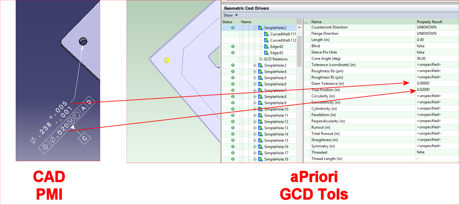
To confirm that the expected PMI values have been correctly imported, go to the Geometric Cost Drivers pane and navigate to a GCD that should have the PMI value from the CAD model.
-
In this example, note that the “+.005/-.001” CAD PMI tolerance appears in aPriori as a total “.006” tolerance.
-
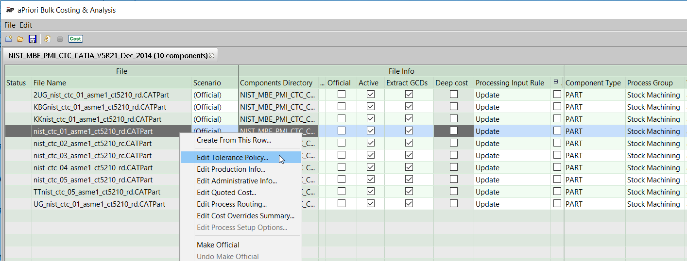
For Interactive Bulk Costing, you must set the Tolerance Policy for the Bulk Costing run for all or selected scenarios. You can specify the Tolerance Policy from the command line or from the input spreadsheet.
Supported CAD systems and PMI Types
aP Pro can import semantic PMI values from native-format files for these CAD systems:
-
CATIA
-
Creo
-
NX™
-
SOLIDWORKS™
aP Pro can also import semantic PMI values from STEP files generated by recent versions of NX, CATIA, SolidWorks, Inventor. See STEP Support.
The following types of PMI are generally supported, with some restrictions for different CAD systems:
-
Diameter tolerances, including ISO hole and shaft tolerances and fits
-
Most geometric tolerances
-
Surface Roughness Ra & Rz
-
“Virtual” Threads/Taps (see Import Threads )
STEP Support
aPriori supports extracting semantic tolerance information from the following CAD systems and versions:
-
NX 2406 and higher
-
CATIA V5-6R2024 (R34) and higher
-
SOLIDWORKS 2024 and higher
-
Inventor 2024 and higher
Note: Known Limitation: aPriori does not import virtual thread and tap information from STEP files.
aPriori does not support extracting semantic tolerance information from STEP files generated by the following CAD systems:
-
CREO
-
SolidEdge
While some tolerance annotations may be imported into aPriori from those STEP files, results were too inconsistent or incomplete to be able to claim support. We have determined that often the STEP file itself did not include the expected PMI information, or the information was not correctly specified in compliance with the STEP AP242 standard. These STEP export issues from Creo have been reported to PTC.
A summary of the issues frequently observed with STEP exports from Creo include:
-
Tolerance annotations are associated with edges rather than surfaces, when exported from Creo to STEP AP242.
-
Tolerance annotations that reference multiple features in native Creo will reference only a single feature in the STEP export.
-
Tolerance annotations attached to dimensions are not exported from Creo to STEP AP242.
-
Composite tolerance annotations are not exported from Creo to STEP AP242.
APriori has not yet evaluated the quality of semantic tolerances exported from SolidEdge to STEP AP242 so cannot claim support. Please contact aPriori Support or your aPriori account team if supporting SolidEdge tolerances via STEP is important to your company and workflows.
Processing Multiple Tolerances for a Single Frame
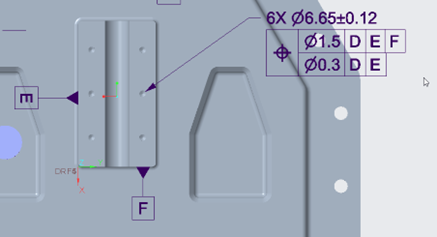
When multiple tolerances are applied to a single composite tolerance frame, aP Pro imports the lowest (tightest) tolerance value listed. For example, with the position tolerance shown below, aP Pro now will import a tolerance of 0.3:
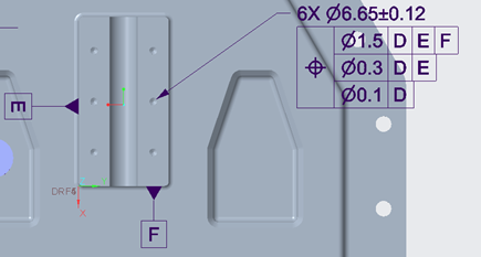
Note: there is a known limitation for Creo and Catia CAD models that allows aPriori to read only the first two tolerances specified in a composite tolerance frame. Hence, if the example above was extended to have three positional tolerances, then the third tolerance value of 0.1 would not be imported, despite being the lowest (tightest) value:
Processing Annotations Referencing Other Tolerances
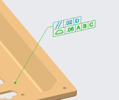
aP Pro correctly imports values from tolerance annotations that reference only other tolerances.
For example, the Profile of Surface tolerance shown below references only the parallelism tolerance to which it is attached. aP Pro assigns the designated surface both a parallelism tolerance value and a profile of surface tolerance value:
Import Threads
aP Pro can import threaded information from the CAD model, in the same way as importing tolerance information.
Note: Threads are not extracted for any CAD STEP242 export.
CAD systems allow you to define virtual (non-modelled) threaded holes or shafts:
-
As a property or set of properties of a hole feature, typically implemented as a checkbox that says “threaded”, plus fields for entering other data such as thread length or depth pitch.
-
As a separate distinct feature. These features are named differently in different systems - for example, in CREO as “cosmetic thread”.
aP Pro currently supports all these methods, and costs threads based on the fact that the hole is threaded and uses the diameter and the thread length to compute cycle time. Other data such as thread pitch is ignored.
Note: aP Pro does not import PMI from Assembly models, just part models. This includes thread information for holes created as assembly features rather than part-level features. However, if you are working in the Creo Direct Integration version of aP Pro, information about threaded holes made as assembly-level features is provided to aP Pro. In all other cases, users have to indicate that these holes are threaded inside the aP Pro application.
Import Roughness Values
aP Pro can import and process roughness (Ra and Rz) values in a CAD file.
Up to nine Roughness Related fields may be populated across the varying CAD systems supported by aPriori: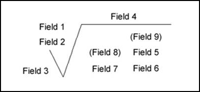
Where the following fields represent:
-
Field 1: Roughness value Ra
-
Field 2: Unused
-
Field 3: Minimum material removal
-
Field 4: Production method
-
Field 5: Roughness cutoff
-
Field 6: Roughness value other than Ra, Rz
-
Field 7: Direction of lay
-
Field 8: Rarely used.
-
Field 9: Rarely used.
Roughness Processing
aP Pro looks at any values defined in these nine fields according to the following rules:
-
Find all fields that look like "Ra number" (case insensitive and ignoring whitespace around "Ra" and around the number).
-
Find all fields that look like "Rz number" (case insensitive and ignoring whitespace around "Rz" and around the number).
-
If Ra and/or Rz is found then aPriori uses the smallest value of each for the GCD properties.
-
If neither Ra nor Rz is found, then aPriori tries to parse the contents of Field 1 and Field 6 as numbers.
-
Field 1 contains "Roughness value Ra", Field 6 contains "Roughness value other than Ra".
aPriori uses any number in Field 1 for the RoughnessRa property and any number in Field 6 for the RoughnessRz property. -
For example, if Field 1 (the nominal Roughness Ra field) is populated with "32" and Field 5 (the Roughness Cutoff field) is populated with "Ra 64", aPriori use Field 5 since it contains the Ra string and Field 1 does not, even though the VALUE of Field 5 is larger than the value of Field 1.
-
Troubleshoot PMI import
aPriori writes entries to the log file whenever it encounters a PMI attribute that it cannot map to a GCD. The following messages are “WARN” level and, by default, are written to the log file:
<PMI NAME> ignored because it is specified on an inactive surface,
<PMI NAME> was not associated with any GCDs, and
<PMI NAME> was not used because it is not semantic and has no magnitude. It would have been associated with GCD(s) <LIST OF GCDs>
To reduce the number of entries written to the log files, several other PMI messages are only written if the logging is set to DEBUG level.
Set DEBUG-level logging for PMI
-
Open <apriori_install>/log4j.properties in an editor.
-
Add the following line: log4j.logger.com.fbc.util.cad.pmi.PmiLog=debug
-
Save the file and restart aPriori.
View PMI log messages
-
Click Help > Explore Logs Directory
-
Open apriori.log in a text editor. Search for entries with PmiLog.
-
These messages contain information that enable you to identify the PMI attribute that failed and the reason, as shown in the following example.
DEBUG PmiLog:285 - [Dim tolerance NIST PMI FTC 06 ASME1|Annotation Set.1|Linear Size.30 LINEAR 7.9375[-0.508:0.508]] were ignored because aPriori currently does not support non-radial/diametrical dimensional tolerances.
-
Since aPriori imports only semantic PMI, and since it is not always easy to identify semantic vs. non-semantic PMI in a CAD system, aPriori logs entries like the following when it encounters non-semantic PMI attributes:
WARN PmiLog:285 - Gtol turning|Annotation Set.1|Geometrical Tolerance.13 [SYMMETRY -1] Note:.0005|| is not semantic
-
More resources
Please consult the information for your CAD system to understand how to use PMI, as some CAD systems may require you to acquire and install an additional module for creating PMI annotations. For example, CATIA requires that you have access to their Functional Tolerancing and Annotation module.
For more information, refer to:
-
Reputable third-party sites such as the National Institute of Standards and Technology (NIST, http://www.nist.gov).
-
The PMI sections of the documentation, training, and Support resources for your CAD system(s)