Slot GCD
Slots are volumetric GCDs that fall into two categories:
• Standard slots: generally have flat or semi-circular floors, with parallel walls normal to the floor. A standard slot can have open, cylindrical, or bathtub ends, or the slot can form a closed loop. A standard slot can also have no floor and parallel walls (a through slot).
• Dovetail slots: have flat floors and parallel walls. Either both walls are undercut (that is, tilted in, over the floor) or one is undercut and the other is normal to the floor. The height of a given wall cannot vary along the length of the slot. Either the slot ends are both open, or the slot forms a closed loop.
For more information, see the following sections:
Standard Slots
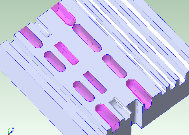
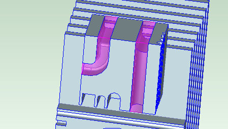
Standard slots have parallel walls. Each wall can vary in height, and the walls can be different heights from each other. Some standard slots have flat or semicircular floors, and some slots have no floor. If a slot has a floor, the walls are normal to it. The image below shows slots (in purple) with flat floors:
The image below shows slots (in purple) with semi-circular floors:
A flat floor cross-section normal to the walls and floor is a line. A semi-circular floor cross-section normal to the walls and floor is a semi-circle.
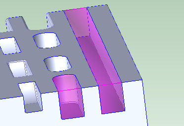
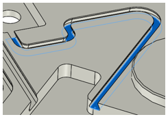
The following image shows a slot with no floor and cylindrical ends:
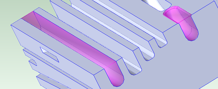
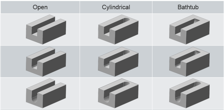
Each end of a standard slot can be open, cylindrical, or bathtub. The image below shows slots (in purple) with one or two ends:
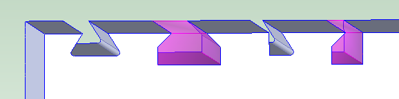
The slots shown below are all open on one end and the other end is either open, cylindrical, or bathtub. For each, a flat floor with and without fillets is shown, as well as a semi-circular floor:
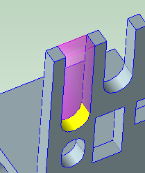
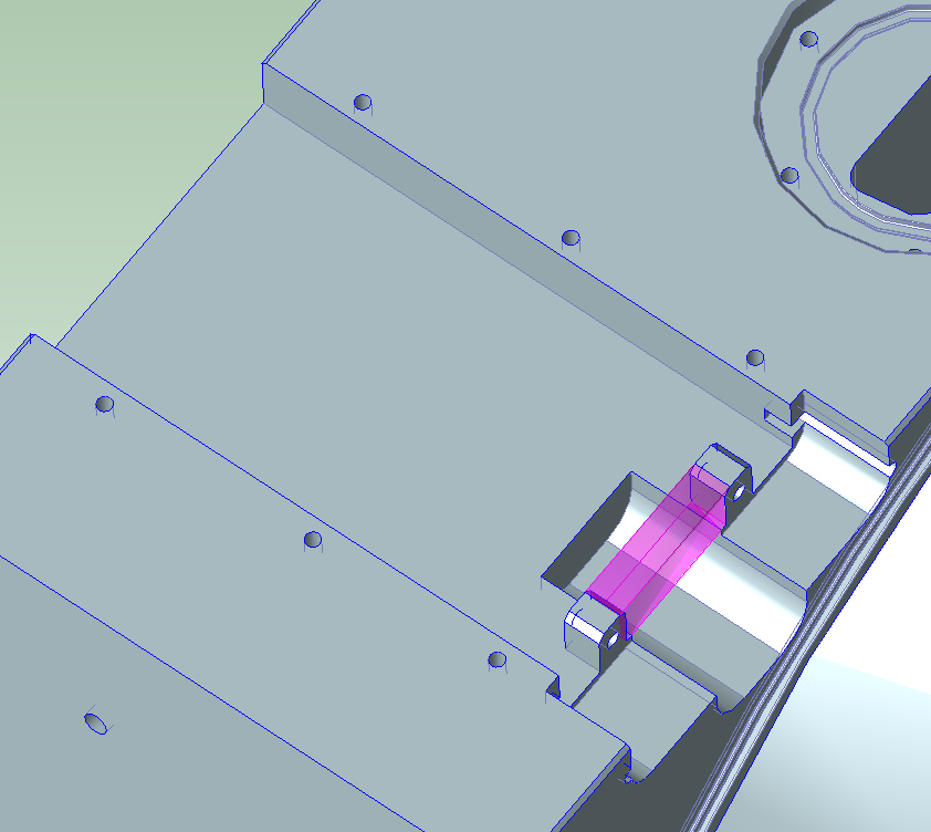
Sometimes, a feature that might be interpreted as a through slot with an open end is recognized as a short, deep slot, which allows for more appropriate operation assignment. The slot below (highlighted in purple) has a semi-circular floor (shown in yellow):
A standard slot might also form a closed loop.
Dovetail Slots
Dovetail slots have flat floors and either walls with symmetric undercuts or (for half-dovetail slots) one wall with an undercut and one wall normal to the floor. The walls can be different heights from each other. The height of a given wall cannot vary along the length of the slot; that is, for a given wall, the wall height at a given point along the length of the slot must be the same as the height of that wall at any other point along the length of the slot. Dovetail slots are open on both ends, or else form closed loops. They are assumed to be created with the help of a special finishing tool whose geometry matches the wall undercut(s).
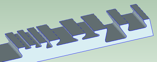
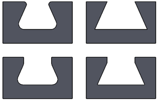
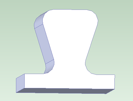
The following image shows various dovetail slots with undercuts in both walls:
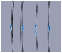
The highlighted GCDs in the following images are half-dovetail slots (with an undercut in only one wall):
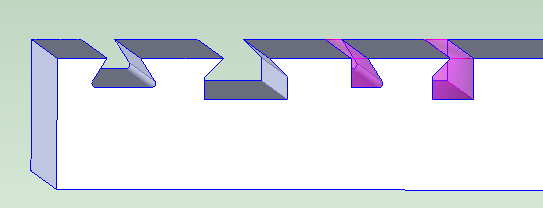

The highlighted GCDs in the following images are modified dovetail slots, whose undercut walls have a vertical portion beneath the undercut:

Dovetail slot corners can have fillets and slot walls can have rounds. A portion of the top of the walls can be normal to the floor.
Dovetail slots can have associated drop holes, which create room for a finishing tool to be moved into position (drop holes are only recognized as such by the cost model for closed loops).
Pitch and Yaw
Standard slots can have pitch, and slots of both kinds can have yaw.
• A slot has pitch if its trajectory curves up or down at any point (that is, if the lengthwise edges of the floor do not both lie in a single plane).
• A slot has yaw if its trajectory curves to the side at any point (that is, if each wall—or the undercut portion of each wall, for dovetail slots--does not lie in a single plane).

But note that, for a dovetail slot, any two cross-sections (in planes normal to the walls and floor) must be the same size and shape.
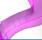
Note also that for a slot with pitch, the floor can be made of multiple surfaces. In the image below, the slots shown in purple pitch downward, and each has a floor composed of two different surfaces:
A through slot (one with no floor) and no yaw cannot have an open end.
Slot Surfaces
The surfaces that make up the slot floor, walls, and ends are not child GCDs of the Slot GCD, but they are associated with the slot through the following GCD relations:
• Is Floor Of
• Is Wall Of
• Is End Of
Other surfaces that can be part of slot are also not child GCDs of the slot, but are related to it by the following GCD relations:
• Is Chamfer Of
• Is Round Of
• Is Fillet Of
Slot Properties
The following diagram shows some of the important slot properties for dovetail and standard slots:

Following are the properties that appear for Slots in the Geometric Cost Drivers pane:
• Depth A: maximum depth of one wall. Depth is measured along a line that is normal to the floor, from the top of the wall to the floor’s lowest point.
• Depth B: maximum depth of the other wall. Depth is measured along a line that is normal to the floor, from the top of the wall to the floor’s lowest point
• Dovetail Depth A: for dovetail slots only. This is the depth of the undercut portions of the slot. It is measured along a line that is normal to the floor, from the top of the undercut. For half-dovetail slots, this maybe null or 0.
• Dovetail Depth B: for dovetail slots only. This is the depth of the undercut portions of the slot. It is measured along a line that is normal to the floor, from the top of the undercut. For half-dovetail slots, this maybe null or 0.
• End1 Type: indicates whether one slot end is OPEN, BUTHTUB, or CYLINDRICAL. If the slot forms a loop, this is LOOP.
• End2 Type: indicates whether the other slot end is OPEN, BUTHTUB, or CYLINDRICAL. If the slot forms a loop, this is LOOP.
• End1 Length: length of one bathtub or cylindrical end. This is 0 if the end is open or if the slot forms a loop.
• End2 Length: length of the other bathtub or cylindrical end. This is 0 if the end is open or if the slot forms a loop.
• Has Pitch: true if the slot trajectory curves up or down at any point (that is, if the lengthwise edges of the floor do not both lie in a single plane); false otherwise. Has Pitch is always false for through slots.
• Has Yaw: true if the slot trajectory curves to the side at any point (that is, if each wall does not lie in a single plane); false otherwise.
• Length: length of the slot floor, measure from one end to the other. This does not include the lengths of any bathtub or cylindrical ends.
• Number of Undercut Sides: This is 1 if and only if the slot is a half-dovetail slot (with only one undercut wall). Note that this is 1 if and only if either Undercut Width A or Undercut Width B (but not both) has a value greater than 0.
• Major Diameter: For dovetail slots only. This is the width of the slot, including fillets (if present), measured along the floor in a plane normal to the walls and floor.
• Min Floor Diameter: the diameter of the tightest upward curve in the slot floor and ends. That is, the maximum tool diameter required for any bathtub end or upward pitch in the slot floor.
• Slot Type: For dovetail and half-dovetail, the value of this property is DOVETAIL.
For modified dovetail slots (which have vertical wall portions beneath the undercuts), the value of this property is DOVETAIL_A.
For standard slots, this property indicates the slot’s floor type:
o STRAIGHT_FLOOR : the floor cross-section, in any plane normal to the walls, is a line.
o SEMICIRCULAR_FLOOR: the floor cross-section, in any plane normal to the walls, is a semi-circle.
o THROUGH: the slot has no floor. (Such a slot must not have an open end.)
• Top Round Radius A: radius of the round on the top of one wall.
• Top Round Radius B: radius of the round on the top of the other wall.
• Throat Diameter: for dovetail slots only. This is the diameter the slot’s drop hole, if there is one; that is, this is the diameter of the largest circle that can fit in the drop hole opening. The value is -1 if the slot has no associated drop hole.
• Undercut Width A: for dovetail slots only. This is the width of the undercut portion on one side of the slot, measured along the floor in a plane normal to the walls and floor. For half-dovetail slots, this maybe null or 0.
• Undercut Width B: for dovetail slots only. This is the width of the undercut portion on the other side of the slot, measured along the floor in a plane normal to the walls and floor. For half-dovetail slots, this maybe null or 0.
• Volume: slot volume. This is the volume of material expected to be removed in order to create the slot.
• Wall Angle A: angle between one wall and the floor. This is 90 degrees for standard slots, and less than 90 degrees for dovetail slots. This is the same as Wall Angle B.
• Wall Angle B: angle between the other wall and the floor. This is 90 degrees for standard slots, and less than 90 degrees for dovetail slots. This is the same as Wall Angle A.
• Width: distance between the tops of the slot walls, measured in a plane normal to the walls and floor. Note that for a dovetail slot, this is different from Major Diameter, which is the width along the floor.
Geometries Not Recognized as Slots
Following are some examples of geometries not recognized as slots:
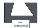


The following geometry has volumes on either side that might be thought of as slot-like, but they are not recognized as Slot GCDs:
No through slots with two open ends are recognized. For example, no through slot connecting two through holes (whose diameters exceed the slot width) are recognized.
A volume with walls won’t be recognized as a slot if the distance between the walls varies (for example, due to modelling errors).
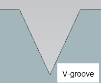
aPriori does not recognize slots whose ends are not bathtub, cylindrical, or open. For example, aPriori does not recognize slots that end at a planar face instead of a curved wall with diameter equal to slot width; such a slot cannot be made with typical slot-making operations. In such cases, the feature may instead be recognized as a pocket, and pocket roughing settings can be adjusted to mimic a slot-making operation.
In addition, by default, the following types of volumes are not recognized as slots:
• Volumes that are too wide (compared to depth or length)
• Volumes with openings in the floor that are too large (compared to floor area)
• Volumes whose walls are very different lengths.
The thresholds that help define these types of volumes are controlled by Slot Site Variables that Define Recognition Thresholds.
If a slot-like feature is not recognized as a slot because of these constraints, it might be recognized as a pocket, or included in the BulkRemoval GCD.
Slot Site Variables that Define Recognition Thresholds
This section lists several types of volumes that are not recognized as slots. The thresholds that help define these types of volumes are specified by site variables in the Machining process group, as described below:
• Volumes that are too wide compared to their length: a volume is considered too wide compared to its length if its width-to-length ratio exceeds the value of the site variable slotMaxWidthToLengthRatio (15.0 by default).
To allow recognition as slots regardless of width-to-length ratio (except for wide slots—see below), set slotMaxWidthToLengthRatio to -1.
• Wide, flat, open volumes that are too wide compared to their length: a volume is considered wide if the following holds:
o Width exceeds the value of the site variable wideSlotWidthMm (50mm by default).
A wide volume with a flat floor that is open on both ends is considered too wide compared to its length if the following holds:
o Width divided by length exceeds the value of the site variable wideSlotMaxWidthToLengthRatio (2.0 by default).
To disable this constraint on slot recognition, set wideSlotMaxWidthToLengthRatio to -1.
• Volumes that are too wide compared to their depth: a volume is considered too wide compared to its depth if its width-to-depth ratio exceeds the value of the site variable slotMaxWidthToDepthRatio (100.0 by default).
To allow recognition as slots regardless of width-to-depth ratio, set slotMaxWidthToDepthRatio to -1.
• Flat volumes with openings in the floor that are too large: for a volume with a flat floor and without undercut walls, the openings in the floor are considered too large if the openings' area divided by the floor's area exceeds the value of the site variable slotMaxFloorHoleRatio (0.8 by default).
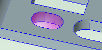
By default, the purple volume below is not recognized as a (short, wide) slot, because it is positioned over a large floor opening.
To allow recognition as slots regardless of the ratio of opening area to floor area, set slotMaxFloorHoleRatio to -1.
• Volumes whose walls are very different lengths: the lengths of a volume's walls are considered too different if the ratio of the lengths exceeds the value of the site variable slotMaxWallLengthRatio (5.0 by default).
To allow recognition as slots regardless of wall-lengths-ratio, set slotMaxWallLengthRatio to -1.
If a slot-like feature is not recognized as a slot because of these constraints, it might be recognized as a pocket or included in the BulkRemoval GCD.
Site Variable that Disables or Enables Half-Dovetail and Modified Dovetail Recognition
To disable geometry extraction for half-dovetail Slot GCDs (which have only one undercut wall) and modified dovetail Slot GCDs (which have vertical wall portions below the undercuts), set slotExtraction2Enabled to false. The site variable is true by default.