The Issues tab identifies Geometric Cost Drivers (GCDs) that created issues with analysis, which made it difficult (Design Warnings), time consuming, or impossible (Design Failures) to manufacture the component using the selected material, Process Group, and Digital Factory.
Issues can include GCDs that:
-
Violate manufacturing standards
-
Are physically impossible to manufacture
-
Require excessive cycle time
-
Require special finishing processes
View and examine issues organized by type or severity to help prioritize design guidance.
Examine When Grouped By Severity
Select Group By Severity to organize issues by severity classification. Expand a severity classification to view all issues in the group:
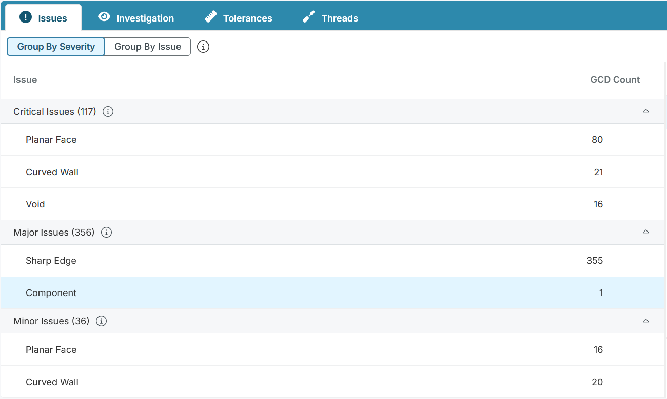
Severity classifications include:
-
Critical Issues: Issues that make a feature unlikely to be manufacturable
-
Major Issues: Issues that pose a high risk of quality defects
-
Minor Issues: Issues that pose some risk of quality defects
-
Cost Drivers: Issues that require additional or specialized processes and/or tooling driving additional costs
-
Unclassified: Issues that do not have a defined severity
Note: Severity classification is currently available in the Plastic Molding, Forging and Sheet Metal Process Groups. Issues that do not have an associated manufacturability score appear under Unclassified.
Tip: Configure the Explore View to add the Manufacturability column and show the highest severity issue detected for each scenario.
Examine When Grouped By Issue
Select Group By Issue to group issues by type. Expand the issue nodes to view issue categories and the types of GCDs affected:
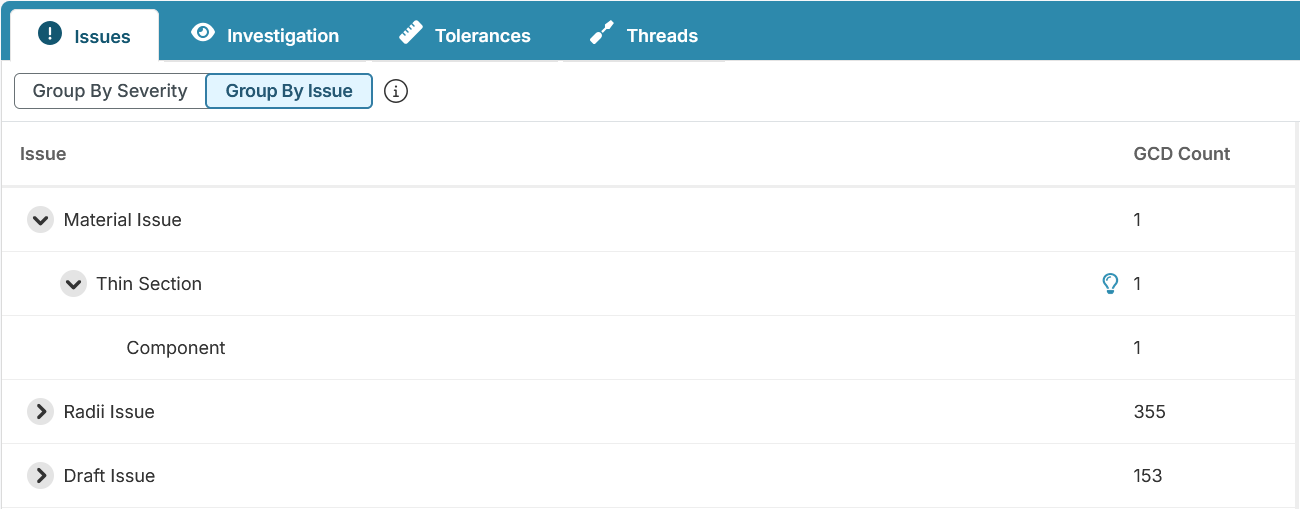
For this example, one GCD has a Thin Section issue in the Material category
View More Guidance
If a light bulb button, , appears next to a type of issue, click it to open a dialog that includes additional information that can help you understand and resolve that type of issue.
Reviewing GCDs with Issues
Select an issue in the table to see more information and to highlight the affected GCDs in the 3D Viewer. The right pane displays a brief description of the selected issue. For example, the description for this Draft issue indicates that the draft angle, 0.5 deg, may affect the surface finish:
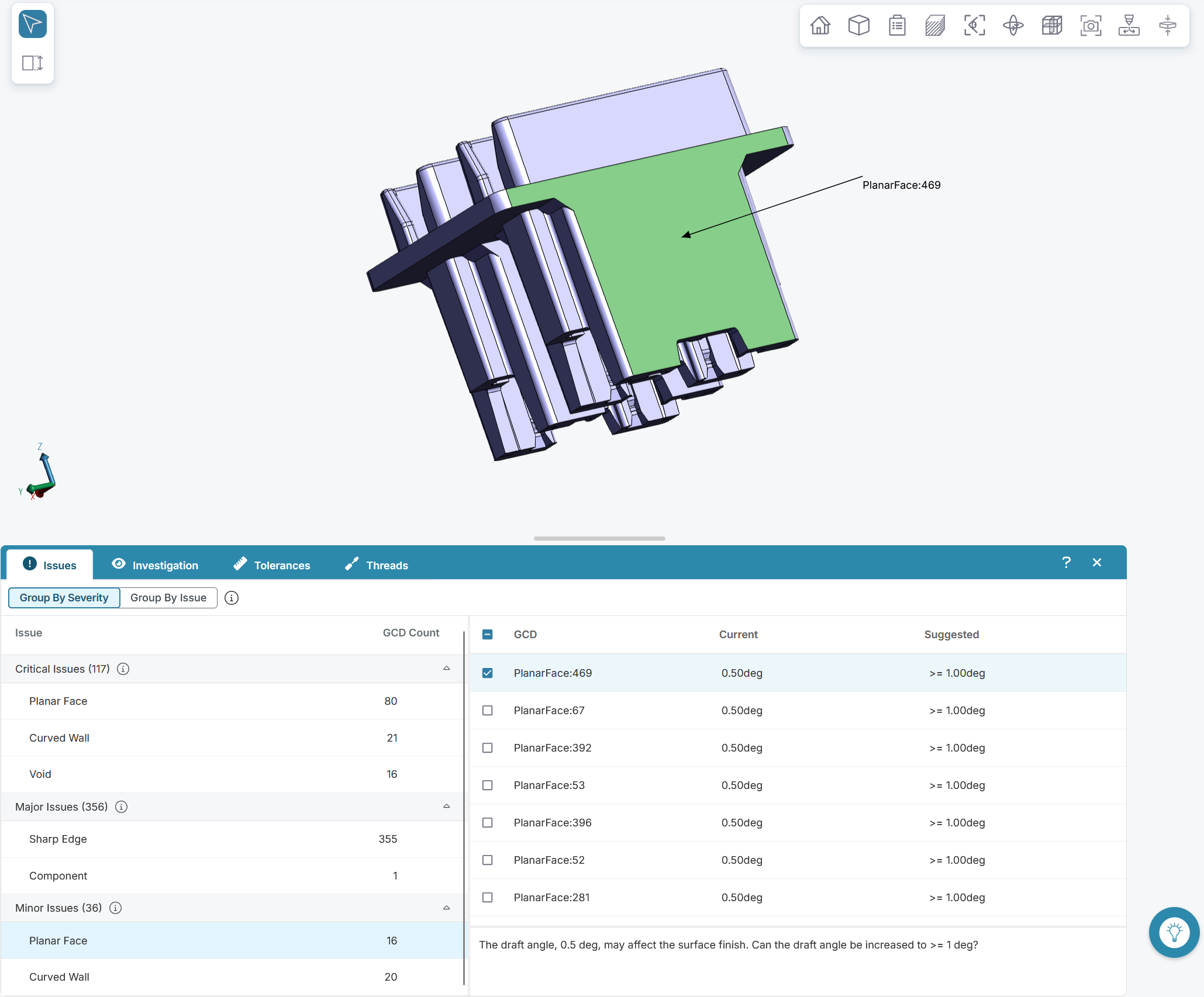
For quantitative issues, the table contains the Current value and the Suggested value. Use the check box in the table header to turn highlighting on or off for all GCDs associated with the issue. To control highlighting for individual GCDs, select or deselect the check boxes in the corresponding rows.
Tip: To better examine GCDs in the 3D Viewer, use the Analysis > GCD Labels options in Toolbar. Learn more about the 3D Viewer Toolbar.