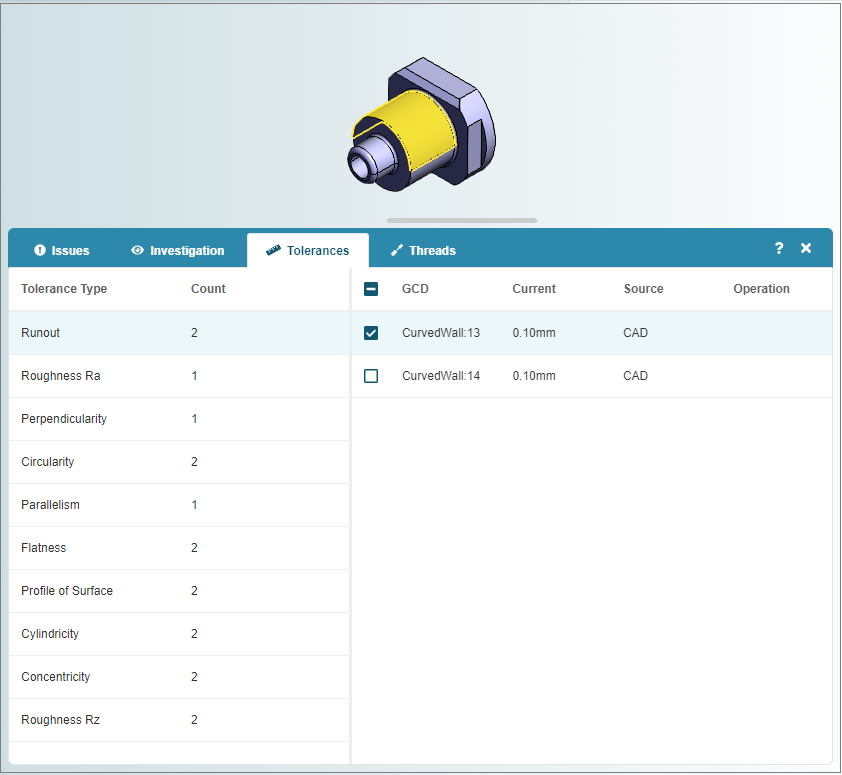
The Tolerances tab allows you to review the requirements for toleranced GCDs:
The left pane of the Tolerances tab contains a table that categorizes tolerances by type and indicates the Count, or number, of GCDs for which each Tolerance Type is applied. For details of supported tolerances, see Set Default Values and Configure Preferences.
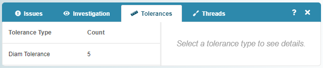
View Tolerance Details
When you select a Tolerance Type, relevant GCDs appear in a table on the tab and in the Viewer:
The table includes:
-
GCD: the name of the GCD.
-
Current: the current tolerance value.
-
Source: tolerance source, that is whether the tolerance was specified in the CAD file for the scenario or as a Policy in the aP Pro or aP Design settings.
-
Operation: process that the tolerance applies to.
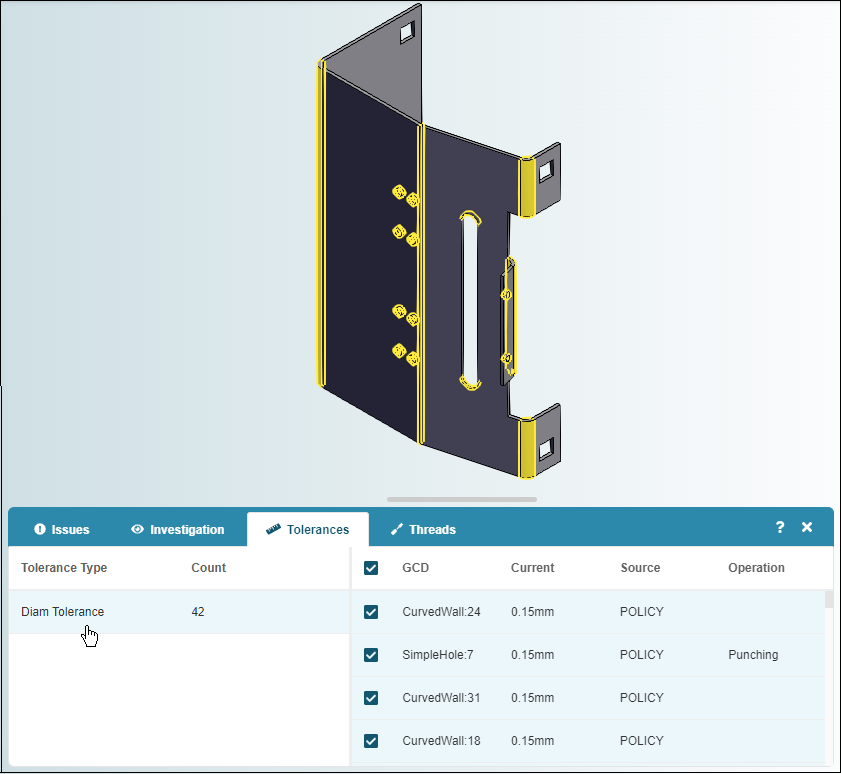
For the scenario in this example, 42 GCDs have a diameter tolerance (Diam Tolerance). The tolerance requirements are due to a Policy in the aP Design settings.
Note: Changes to tolerance requirements in the aP Design settings are not applied to existing scenarios even if the CAD file is updated. Tolerance changes only apply to CAD files that you upload after changing the settings.
This example shows the Tolerances tab for a different scenario which includes Geometric Dimensioning and Tolerancing (GD&T) that aP Design extracted from a CAD model: