aPriori 2022 R1 provides the following enhancements:
-
New Cost Model for Compression Molding of Sheet Molding Compound (SMC)
-
New view in Plastic Molding Tooling Reports shows slide locations
New Cost Model for Compression Molding of Sheet Molding Compound (SMC)
aPriori 2022 R1 provides a new cost model for estimating the manufacturability and cost of parts made from Sheet Molding Compound (SMC) material via the Compression Molding manufacturing process. This cost model is separately licensed and accessed via a new routing in the Plastic Molding process group.
SMC Compression Molding is used to manufacture large fiber-reinforced plastic components, typically of relatively consistent wall thicknesses, across a wide range of industries. Some key benefits of this process include
- High production volumes
- Excellent reproducibility
- Low scrap
- Low labor cost
- Large parts
- Lightweight, low-cost alternative to sheet metal
- Simpler and cheaper tooling compared with injection molding
Of particular note, the use of SMC Compression Molding to make body panels, covers, and housing for automotive vehicles and agricultural equipment is increasing, replacing the use of sheet metal and resulting in parts that are lighter, cheaper, and do not rust.
SMC is a category of high-strength composite materials, commonly consist of a thermosetting resin (e.g. polyester, vinyl ester, or epoxy), reinforced with chopped fibers (for example, glass, aramid, or carbon). The SMC material can be tailored to meet specific requirements. Through the use of specific additives, the final part properties can have enhanced structural properties, electrical resistance, flame retardancy, sand pigmentation. The raw SMC material is provided in rolls and has a dough-like consistency.
The picture below illustrates the main steps in the SMC Compression Molding process:
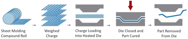
Figure: Compression Molding Process
- SMC material is cut from a roll using a standard knife and weighed to a create a specific “charge” which is loaded into the mold tools. The charge can be a single piece or multiple pieces which are distributed throughout the mold tool. The material charge is NOT cut into a "blank" that corresponds to the shape of the final part, it is just the required mass of material.
- The metal mold tools, which are mounted within a hydraulic press, are heated to enable curing of the material. The matched tooling closes to compress the material charge and disperses the material throughout the mold cavity. The heated press remains closed to allow the part time to cure; this typically takes between 5-10 mins depending on part thickness and resin properties. The required cure time is ultimately determined by the maximum part thickness as any material which is not cured during this process will be remain in a viscous state
- The part is removed from the mold.
- Flash typically is produced at the parting line of the tool. Flash is removed either manually using a hand-held tool or via a CNC router or Waterjet process.
aPriori assesses the manufacturing approach and estimates the main cost drivers of producing SMC Compression Molded parts -- process time and cost, material cost, and tooling cost – described as follows:
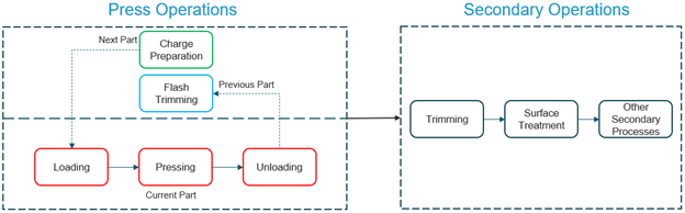
Figure: Press Operations and Secondary Operations
-
Press operations include cutting and weighing the material charge, tool cleaning, release agent application, loading of the material charge, mold open/close, pressure application and curing, part unloading, and optional flash trimming with some operations conducted in parallel as illustrated above. Pressing/curing time is generally in the range of 5 - 10 minutes or more. While the part cures, the operator prepares a charge of material for the next part, and optionally trims flash manually (using a hand-held tool)* from the last part removed from the mold. The cycle time for the press operation is computed as the greater of the time for (Loading, Pressing, Unloading) and (Charge preparation and Manual Flash Trimming), which is displayed in the Custom Output section of the Part Details view:
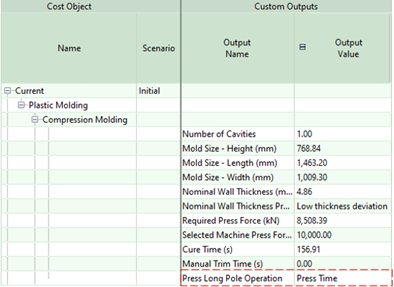
Figure: Custom outputs display the "long pole" - loading, pressing, unloading or charge preparation and manual flash trimming.
-
Secondary operations include Offline Part Trimming and any additional desired surface treatment and other secondary processes. Offline Part Trimming involves the use of either a 5-axis router or a waterjet cutter to remove flash1 and to make any internal holes or cutouts that are not created in the mold. Note that Simple Holes (round holes) are assumed to be created using a secondary trimming process unless manually assigned an 'As Molded' operation.
Note: 1By default, aPriori will assign manual flash trimming when the part has no internal holes or cutouts that require an offline trimming operation. If such features exist, then flash trimming also will be performed by the offline trimming operation. To change the default behavior for a specific part, use the process setup option Include Manual Flash Trimming. To change the default behavior for all parts, set the cost model variable cmAutoIncludeManualFlashTrimming.to false.
As described earlier, the Compression Molding routing is available in the Plastic Molding process group. It will be evaluated automatically if an SMC Material is selected2. The aPriori Regional Data Libraries (RDLs) now include a variety of SMC materials, with different resin systems, fiber materials, fiber volume fractions, and finished weight resins, as shown below.
Regional Data Libraries (RDLs) now include a variety of SMC materials, with different resin systems, fiber materials, fiber volume fractions, and finished weight resins, as shown below
-include-a-variety-of-SMC-materials.png)
Figure: (RDLs)-include-a-variety-of-SMC-materials
Note: 2Note for Digital Factory Managers – if adding additional SMC materials to the Materials table, set the Can CM field to true. This indicates the material is suitable for Compression Molding and drives the automated evaluation of the Compression Molding routing.
Material Utilization and Material Cost are calculated based on the estimated volume of the initial material charge. By default, aPriori assumes that holes and cutouts are made by a Trimming process (router or waterjet) after the part is removed from the mold, and accounts for the additional material needed to "fill in" or "cap" these features in the molded part. Additionally, aPriori accounts for the loss of some material due to flash at the parting line, depending on the mold type.
For a given part, users can change assumptions about whether cutouts are molded or made post-molding can be modified by using the process setup option Internal Cutouts Are Capped. To specify the default behavior for all parts, use the cost model variable cmInternalCutoutsCapped. To specify that internal cutouts are created in the mold instead of made after molding, change the value of these options to false. To specify that Simple Holes (that is round holes) are made in the mold, assign the 'As Molded' operation to the specific holes(s).
Note: Capped cutouts will yield poorer material utilization but faster material loading, as this reduces the need to load and position multiple charge pieces around a shut off cutout.
Capital investment in hard tooling is calculated mechanistically. Compression molding tools are produced by cutting the required geometry into two blocks of tool material (AISI 4140 steel by default), representing the die and punch. The estimated tooling cost accounts for the tool design, materials, machining, labor and purchased items that make up the tool. aPriori provides detailed breakdown of the tooling costs in both the Investments tab and the Tooling spreadsheet report.
One significant factor that influences compression molding tooling cost is the mold closure type. Three types of mold closure are available:
- Flash - this is the cheapest type of closure and allows flash to escape the mold, resulting in a lower material utilization than other closure types
- Semi-Positive - this is the most common type of mold closure, which results in a minimal amount of flash. Flash trimming still is required.
- Positive - the most expensive types of mold to manufacture, positive mold types produce no flash, resulting in the most efficient material utilization and eliminating the need for flash trimming operations.
aPriori assumes a Semi-Positive mold closure type by default (controlled by the cost model variable cmMoldClosureType) but provides a process setup option Mold Closure Type to modify the mold type for a given part.
Note that Compression Molding tooling is simpler than Injection Molding tooling as it does not include side actions. Therefore, any holes or cutouts that are not accessible from the draw direction are made by offline trimming processes after the part is removed from the mold. If the part body itself creates a “die lock” condition, aPriori determines if the amount of die lock is small enough to allow the part to be tilted and/or flexed to enable removal from the mold tooling. If the amount of undercut is sufficiently small, aPriori will provide Design for Manufacturability feedback that an undercut feature (Void) exists but is considered to be feasible to manufacture. If not, the undercut features will fail to cost and aPriori provides DFM feedback that undercut geometry prevents removal from the tool or that internal undercut features are inaccessible and cannot be molded.
See Design Guidance for Compression Molding for more information about other Design for Manufacturability and Design to Cost feedback provided for compression molded parts.
Machines: The aPriori Regional Data libraries provide a set of branded compression molding presses, as well as several virtual machines, which represent an aggregate of the branded machines within a certain size and capability range. The virtual machines range starts from 10,000 kN clamp force with a bed size of 2m x 1.8M up to 50,000 kN clamp force and bed size of 5m x 3m. Branded machines include several models from Accurl and Pengda.
Many of the process setup options available for Plastic Injection Molding also are applicable for Compression Molding. Additionally, new process setup options specific to Compression Molding are provided to adjust the assumptions used the manufacturing and cost estimates:
- Mold Closure Type - allows choice of Flash, Semi-Positive, or Positive mold type affecting tooling cost and material utilization estimates. Semi-Positive is the default.
- Part Ejection Method - allows choice of air poppets (default) or hydraulic ejector pins. Air poppets (the default) are more commonly used as hydraulic ejector pins require a costly dedicated ejector box
- Material Colorant - provides selection of colorants which may be added to the SMC material; cost estimates will include colorant cost (specified in the lookup table cmColorantMaterials).
- Compression Molding Pressure - allows user to choose whether to use the minimum, maximum, or average (default) molding pressure specified for the selected material, or enter another value
- Material Charge Mass - allows user to override the calculated charge mass
- Number of Charge Pieces - Allows user to override the number of charge pieces. The more charge pieces the longer it will take to operator to load them.
- Internal Cutouts Are Capped - Allows user to specify whether cutouts are made by a Trimming process (router or waterjet) after the part is removed from the mold (default behavior), or are molded in. Note that cutouts that are molded still require secondary trimming to remove the flash unless they are being made in a positive type mold
- Include Manual Flash Trimming - When set to true, aPriori will assign manual flash trimming when the part has no internal holes or cutouts that require an offline trimming operation. When set to false, an offline trimming process (router or water jet) will be used to trim any flash.
- Number of Inserted Components and Inserted Component Cost - enables users to indicate if small components such as bearings or threaded inserts are used, the number and cost of these components
Known Limitations
Note the following limitations:
- aPriori 2022 R1 does not fully support estimating the cost of compression molding Bulk Molding Compound (BMC) materials. BMC materials are provided in a bulk (dough-like) form and parts made from BMC typically utilize tool inserts to create undercut geometry. aPriori does not yet account for these process differences, but plans to add support for thermosetting BMC materials in a near future release. aPriori currently does not plan to support thermoplastic BMC materials. Please contact your aPriori account representative or aPriori Support if you require support for thermoplastic BMC materials.
- The compression molding routing is available only for compression molded parts. It cannot be selected for assemblies representing a compression molded part with inserts that were placed in the mold tool.
- Workaround: cost just the part representing the SMC material and use the process setup options Number of Inserted Components and Inserted Component Cost if needed to account for insert costs.
- Internal cutouts in the draw direction are not extracted as a distinct GCD. These cutouts are manufactured by an Offline Part Trim operation (router or waterjet) but are not highlighted when selecting Highlight Associated GCDs for that operation. Be assured that the aPriori estimates do account for the time and cost required to make these cutouts. The Parting Line GCD includes a Projected Opening Perimeter property which represents the internal perimeter length that requires trimming and is used to compute trimming times.
New view in Plastic Molding Tooling Reports shows slide locations
The Tooling Report for parts estimated in the Plastic Molding, Assembly Molding, and Assembly Plastic Molding process groups now includes an additional top-down view of the molded part and the relative locations of any slides required to make undercut features.
To generate the Tooling report for a single-shot Plastic Molding part, select Reports > Spreadsheet Reports > Tooling Report.
For over-molded parts and multi-shot parts cost in the Assembly Molding or Assembly Plastic Molding process groups, select Reports > Spreadsheet Reports > Tooling Report - Assembly Molding.
In aPriori 2022 R1 these reports now contain three worksheets; previously only the first two were provided:
- Plastic Molding- Tooling: displays an itemized list of the mold tooling components and their sizes.
- Mold Tooling Layout: displays top, front, and side views of the mold base, including the various mold components and their dimensions.
- Slides and Lifters: displays a top-down view of the molded part and the relative location of slides. Slide locations are expressed as being on the North, South, East or West side of the part, and the view includes a "compass" symbol to indicate how the part and slides would be oriented in the mold base view shown on the Mold Tooling Layout worksheet.
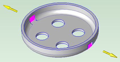
For example, the part shown in the left picture below has two undercuts, which require two side actions in opposite directions as shown in the picture on the right:
|
|
Figure: Undercuts requiring two side actions
For this part, the new top-down view in the Tooling report appears as follows, indicating the presence of slides on the North and South sides of the part:
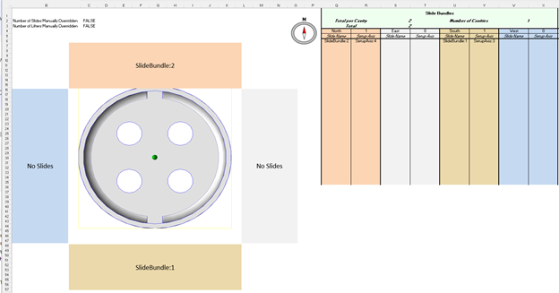
Figure: Top down view in tooling report
If we compare the view above to the top-down view in the Mold Tooling Layout tab of the Tooling report (shown below), we see from the Compass icon that the North direction is pointing to the right in that view. That is, the slides on the North and South sides of the part will travel in the horizontal direction and are located on the right and left sides of the moldbase, in this view. This explains why the mold base horizontal dimension (246.00 mm) is larger than the vertical dimension (218.00 mm), as extra space is needed to accommodate the slides.
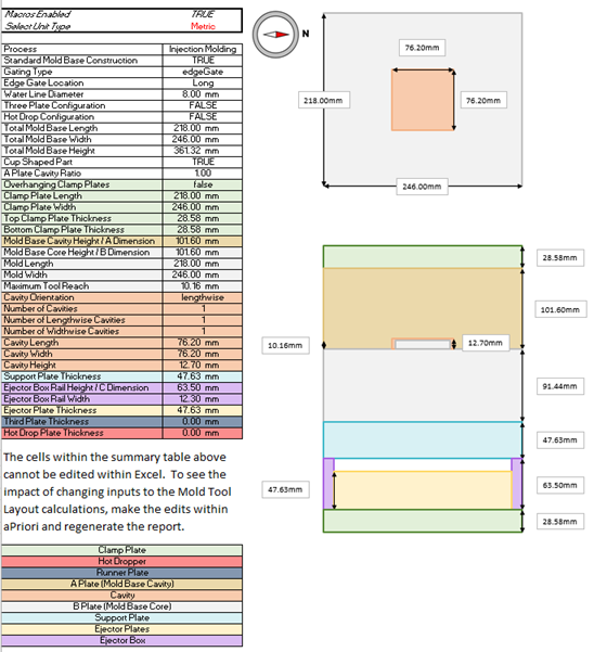
Figure: Top down view in Mold Tooling Layout
The report leverages Visual Basic for Applications (VBA) macros to generate the slide labels, and tabular data in the new Slides and Lifters worksheet as well as the graphical views in the Mold Tooling Layout worksheet. Depending on your security settings in Microsoft Excel, a security warning may be displayed when the report is first opened, as shown in the following image.
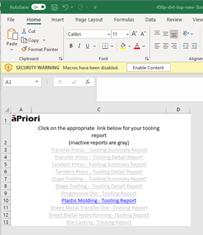
Figure: Tooling report link (security warning)
Click Enable Content to generate the graphical views and populate the tables in these worksheets. If VBA macros are not enabled, the slide labels and graphical views are not generated and the worksheet will instead display text noting that macros are disabled.
For more information about Microsoft security settings and VBA macros, please refer to the topic Enable or disable macros in Office files in Microsoft Excel Help, and consult your company’s IT system administrator for information about company-specific security policies.