Plastic Molding Enhancements
aPriori 2023 R1 provides many enhancements for the Plastic Molding process group, including multiple enhancements for injection molding:
-
-
Average Material Injection Pressure for Cavity Pressure and Required Clamping Force Estimates
-
Industry Standard Values for Material Injection Pressure Boundary Values
-
Explicitly Calculated Plasticizing Times for Injection Molding Cycle Time Analysis
-
Expanded Cavity Finish Options and Improved Estimation of Mold Texturing for Tooling Cost Estimates
-
More Accurate Material Cost Estimates via New Limits for Regrind Material
-
Bulk Molding Compound (BMC) Materials for Compression Molding
Injection Molding
Melt Flow Analysis for Injection Molding, Reaction Injection Molding, and Structural Foam Molding Processes
aPriori now performs a basic material flow analysis for injection molding processes that determines the minimum number of gates required to fill a cavity and more accurately estimates cavity pressure and required clamp force. The improved clamp force calculation results in better machine selection and thus more accurate direct overhead costs.
aPriori 2023 R1 further extends the improvements to estimates of cavity pressure and required machine clamping force that were provided in release 2022 R1 SP1. The cavity pressure is calculated from various inputs including the part wall thickness distribution across the part and the maximum flow length(s) that the melt must travel from the gating locations to the extremities of the part. The 2022 R1 SP1 enhancements improved estimates of the flow length, based on part dimensions and consideration of gate locations. However, aPriori still relied on user input on the number of gates used in the mold and the number of gates was assumed to be 1 by default. If the number of gates was not specified correctly for large parts and other parts that are molded with multiple gates, aPriori clamp force estimates were higher than required. In turn, aPriori could select a larger machine with higher Overhead Rates than required.
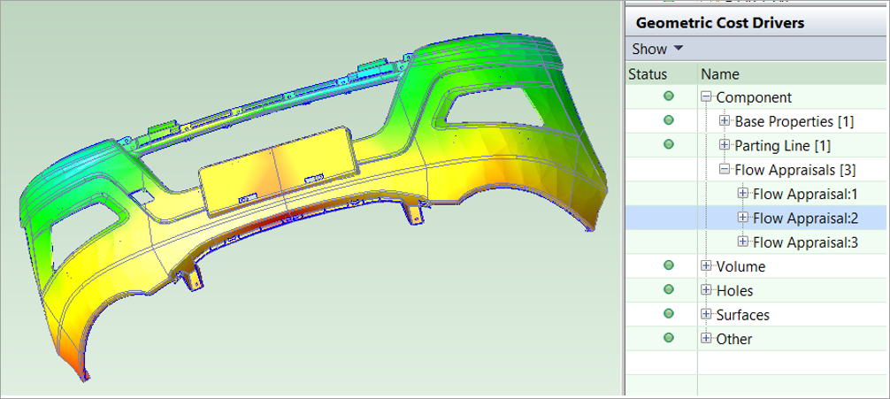
The Geometry engine in aPriori 2023 R1 performs a Flow Appraisal, which is a basic melt-flow simulation that uses the geometry of the part and flow properties of the selected material to automatically determine the minimum number of gates required to fill the cavity, the corresponding cavity pressure, and the required clamp force. As a result of this enhancement, estimates of required clamp force generally will decrease for many parts, particularly larger parts or those with higher length-to-width ratios, compared to previous releases of aPriori. This in turn results in more accurate selection of the lowest-overhead machine that can produce the part, potentially reducing Overhead costs.
To support this enhancement, materials in the Plastic Molding process group now contain a new field, Flow Length Ratio, which is used in the melt flow simulation. The Flow Length Ratio is an experimental index that indicates the distance to which the leading edge of the flow can reach when a specific plastic is made to flow inside a cavity of uniform unit thickness and at a fixed pressure. Materials that flow easily, such as LDPE or PP, have values of ~300 or higher, while more viscous materials have lower values. The aPriori Regional Data Libraries 2023-02 provide values for this field for all the baseline materials. Customers should specify this value for any custom materials in their Digital Factories.
If the Flow Length Ratio is not specified, aPriori uses a conservative default value of 150. If this value is too conservative for the part, aPriori could underestimate the material’s ability to flow and therefore overestimate the number of gates, the cavity pressure, and the required clamp force. The default value for Flow Length Ratio is controlled by the site variable flowLengthRatioDefault.
Flow Appraisal analysis is iterative. It evaluates possible gate locations and determines the minimal number of gates needed to guarantee that all portions of the part can be reached by the melt material before it solidifies. The analysis considers both the Flow Length Ratio of the selected material and the geometry of the part. The analysis does not prioritize the gate placement in terms of manufacturability or cosmetic appearance. As such, the gate locations are not displayed in the diagram.
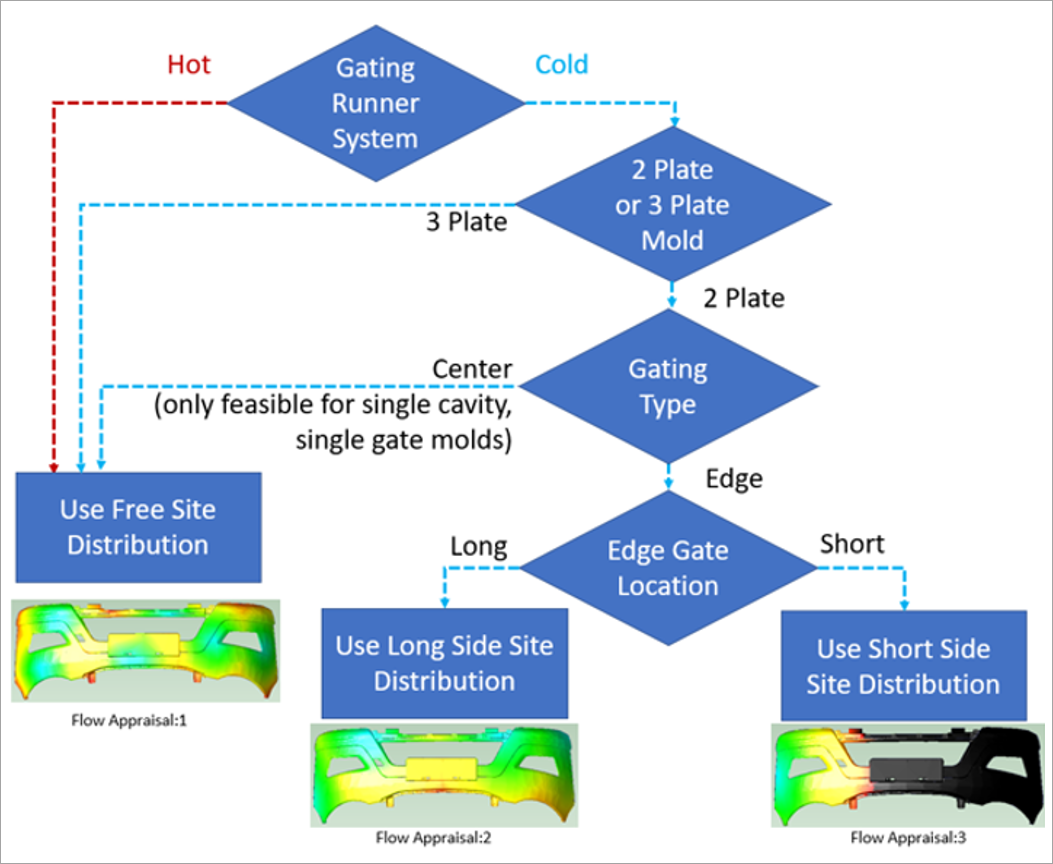
By default, the Flow Appraisal analysis is performed whenever a new part that uses the Plastic Molding process group is analyzed. Flow Appraisal analysis is leveraged in the Injection Molding, Reaction Injection Molding (RIM) and Structural Foam Molding (SFM) routings. These three potential tooling configurations are always analyzed and captured as Flow Appraisal GCDs:
-
Flow Appraisal:1 – considers Gate(s) freely placed within the cavity
-
Flow Appraisal:2 – considers Gate(s) placed on the long edge of the cavity
-
Flow Appraisal:3 – considers Gate(s) placed on the short edge of the cavity
Note: The aPriori Flow Appraisal is a basic melt flow analysis and is not intended to replace specialized mold tool design and analysis software. However, to validate this enhancement aPriori, compared its clamp force estimates to those produced by an industry-leading mold simulation application. A set of ten parts of varying size and geometric complexity were assessed across 16 different baseline materials (Polycarbonate, PC+ABS, Acrylic (PMMA), TPE, ABS, PPS, Acetal, PBT, Nylon (PA6), Nylon (PA66), Nylon (PA46), Polystyrene, Polypropylene, TPO, TPU and PET). For these parts and materials, the average difference in clamp force predicted by aPriori versus the specialized software was only 7%, with a low standard deviation.
Configuration
This table shows the default settings and process setup options that control the tooling configuration that aPriori uses to calculate manufacturability and cost estimates.
The settings were available prior to 2023 R1.
| Tooling Configuration | Default Value | Alternative Value | Controlling Cost Model Variable |
|---|---|---|---|
|
Gating Runner System |
Cold Runner |
Hot Runner |
defaultRunnerSystem |
|
Gating Type for Cold Runner System |
Edge |
Center |
defaultGatingType |
|
Edge Gate Location |
Long |
Short |
defaultRunnerAttachmentSide |
|
Number of Plates in the Mold |
2 |
3 |
– |
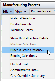
To review or edit the tooling configuration:
-
in the Geometric Cost Driver pane, in the menu bar, select Edit > Process Setup Options.
-
Then, in the Process Options Editor, expand the relevant nodes and select the molding process.
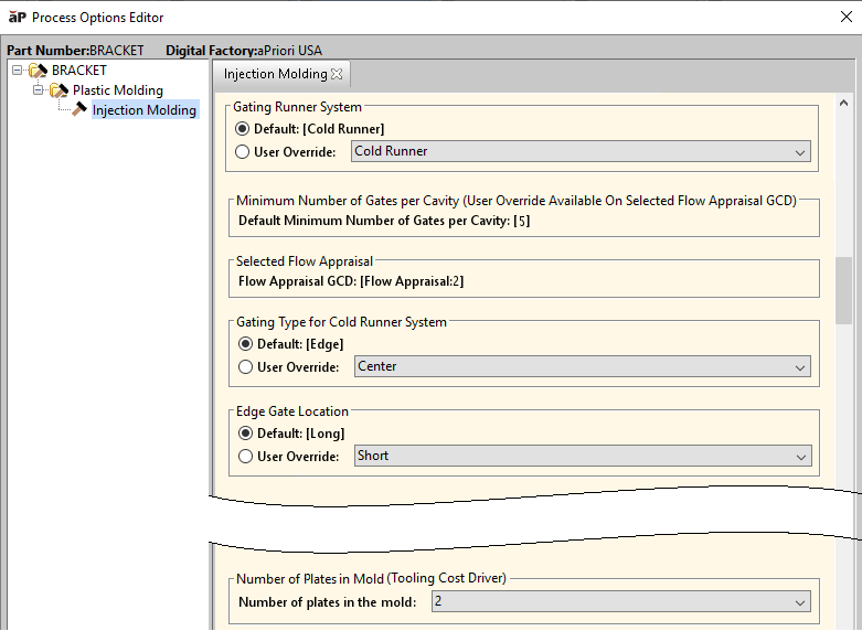
Tip: The calculated values for the Minimum Number of Gates per Cavity and Selected Flow Appraisal are also displayed in the Process Options Editor.
Previous releases included the Number of Gates per Cavity as an editable process setup option for inputting the number of gates. This process setup option is no longer editable in the Process Options Editor. However, you can override the displayed calculated minimum required number of gates:
-
In the Geometric Cost Drivers pane, navigate to and select the Flow Appraisal GCD that aPriori selected.
-
Double click the row that contains the Number of Sites and then edit the value.
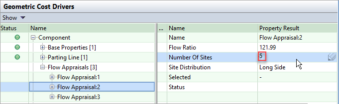
For example, if aPriori calculates that a minimum of 5 gates are required for the specified tooling configuration but you know that 6 will be used in practice, updating the value and recosting the part results in updated estimates of required clamping force, which in turn can influence machine selection and overhead cost estimates.
Caution: If you override the Number of Sites value with a number that is lower than calculated value, it is likely that the costing will fail due to an expected short shot condition. If the costing fails but you still want to evaluate the scenario for a lower number of sites, you can change the feasibility rules for the molding process via the routing editor and then recost the part.
Results
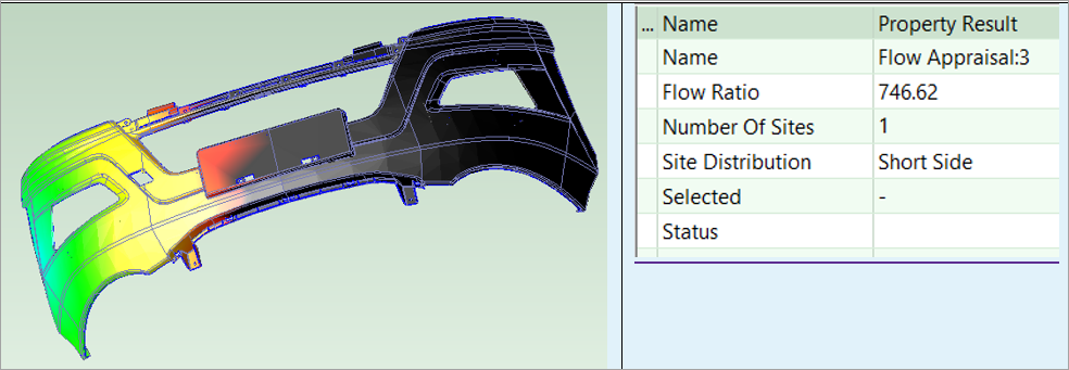
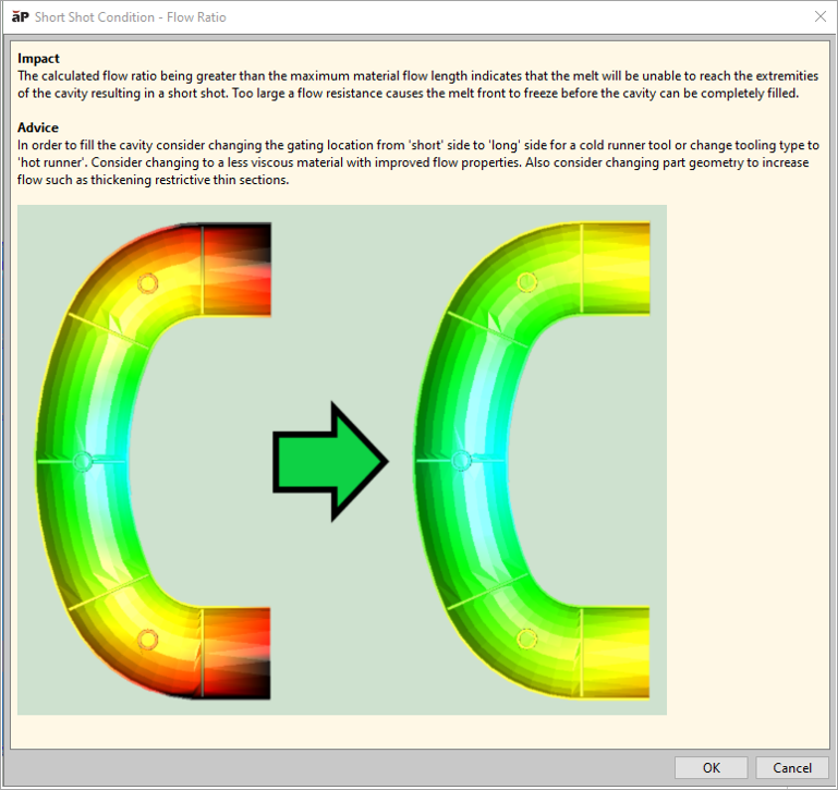
The Flow Appraisal analysis in aPriori Professional generates a 3-D heat map (color-coded representation) of the part that allows you to visualize how material fill the mold for each potential tooling configuration and assumed gate locations.
As this flow chart shows, the heat map results depend on the selected tooling values for the Flow Appraisal.
To open a heat map, in the Geometric Cost Drivers pane, in the Name Column, expand the for Component and Flow Appraisals nodes, and then select the Flow Appraisal that you are interested in.
The blue regions of the part fill first and are less than 10% of the material maximum flow ratio from a gate location. The red regions of the part fill last and are between 90% and 100% of the maximum flow ratio from a gate location.
You can also see the effects of a short shot condition in the Flow Appraisal heat map. For example, the black regions in this figure are for short shot condition that resulted from a Cold Runner system with Edge gates on the short side. Regardless of the number of gates placed along that short edge, the material flow is not sufficient to travel across the length of the part.
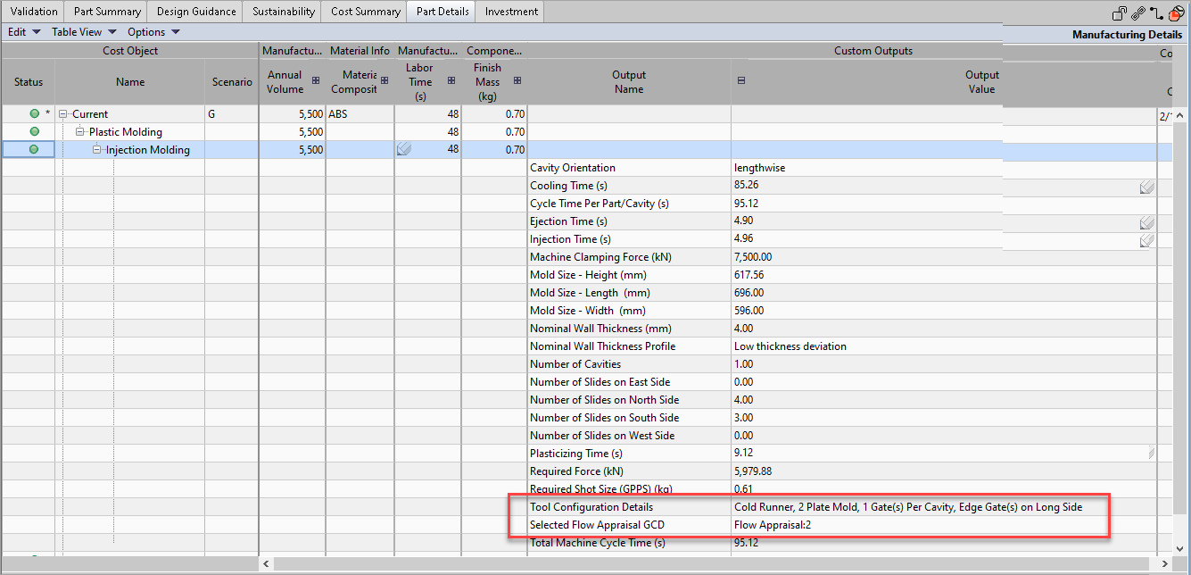
In addition to reviewing these results in the Process Options Editor, as described in Configuration, you can see the calculated values for the MinimumNumber of Gates per Cavity and Selected Flow Appraisal in the Parts Details tab:
-
Open the Parts Details tab.
-
In the Cost Object column, in the Name sub-column, expand the relevant nodes to reveal the molding process.
-
In the Custom Outputs column, expand the nodes for the Output Name and the Output Value sub-columns.
To view the clamp force:
-
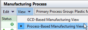
in the Manufacturing Process pane, in the menu bar, select View > Process-Based Manufacturing View.
-
In the Process Step column, expand the relevant nodes to reveal the molding process.
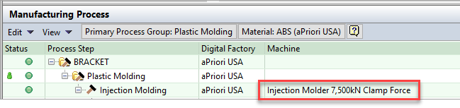
If aPriori calculates that the cavity cannot be filled for the specified tooling configuration regardless of the number of gates, then the costing fails and a warning message indicates the reason for the failure.
A short shot condition is likely to be the reason for costing failures for cold runner systems.
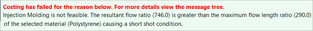
aPriori provides Design Guidance that indicates how to avoid short shot conditions. For example you could change the tool configuration, material, or part geometry.
Impact
In a set of test parts, estimates of required clamp force decreased significantly compared to the previous release of the manufacturing process model, with an average reduction of 39% for both hot and cold runner systems. This reduction sometimes led to the selection of a lower-clamp force, lower-overhead machine.
On average the resulting machine overhead rate decreased by 18% when hot runner systems were specified and 13% for cold runner systems. The resulting decreases in Piece Part Cost were approximately 6.5% and 3.75%, respectively.
Machine selection did not always change compared to the previous release even when required clamp force decreased, either due to other machine requirements or the specific clamp force capabilities available across the various machines in the Digital Factories.
More significant differences in required clamp force estimates were seen for longer, thinner parts and for parts made with higher viscosity materials.
Limitations
The Flow Appraisal analysis is not yet included in the Assembly Molding and Assembly Plastic Molding process groups for insert-molded/over-molded and multi-shot parts, respectively.
Upgrade Considerations
To leverage the Flow Appraisal enhancement, you must upgrade your manufacturing process models to version CMV:220 or higher. To then use Flow Appraisal for a scenario that was cost in previous release or cost model version, the scenario must be connected to the CAD file and the geometry must be re-extracted.
If you do not want to upgrade your cost model at this time, to avoid an unnecessary 9% increase in extraction time, you can disable the Melt Flow simulation by setting the site variable isFlowAppraisalEnabled to False.
Average Material Injection Pressure for Cavity Pressure and Required Clamping Force Estimates
Cavity Pressure and Required Clamping Force calculations now better represent typical manufacturing conditions by using the average maximum and minimum injection pressure values for the material.
In previous releases, Cavity Pressure and Required Clamping Force calculations used the maximum injection pressure value for the material. To better represent typical manufacturing conditions, both calculations now use the average maximum and minimum injection pressure values.
The new process setup option (PSO) Maximum Material Injection Pressure allows you to select or specify an alternative value for the maximum material injection pressure in cavity pressure and clamp force calculations.
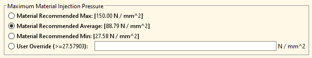
As the figure of the Maximum Material Injection Pressure PSO shows, you can now choose between these options:
-
Material Recommended Max
-
Material Recommended Average (default option)
-
Material Recommended Min
-
User Override – Enter a value that is greater than or equal to the recommended minimum value.
Impact
Due to this enhancement (and to material flow analysis enhancement described earlier in these release notes), estimates of cavity pressure and required clamping force will generally decrease compared to the previous version of the manufacturing process model. This decrease, in turn, may result in the selection of a machine that has lower-clamp-force and lower overhead rates than the machine that was selected for some parts in the previous release.
Industry Standard Values for Material Injection Pressure Boundary Values
The minimum and maximum injection pressure values for several Plastic Molding materials were updated to correspond to standard values used in industry-leading material flow analysis tools.
The Injection Pressure Min and Injection Pressure Max values were updated for several Plastic Molding materials. The updated values are included in the aPriori 2023 R1 starting point Digital Factories and the aPriori 2023-02 Regional Data Libraries.
This table below shows molding material families and indicates those for which the minimum or maximum injection pressure value was updated. Arrows indicate whether the new value is higher (▲) or lower (▼) than the value in the previous release. A dash (–) indicates that the value is unchanged and therefore is not shown.
| Material Type | Injection Pressure Min (MPa) | Injection Pressure Max (MPa) |
|---|---|---|
|
ABS |
– |
– |
|
Acetal |
40 ▼ |
– |
|
Acrylic (PMMA) |
50 ▼ |
– |
|
Nylon (PA46) |
40 ▼ |
150 ▲ |
|
Nylon (PAL) |
55 ▲ |
– |
|
Nylon (PA66) |
55 ▲ |
– |
|
PBT |
70 ▲ |
– |
|
PC+ABS |
50 ▼ |
130 ▲ |
|
Polycarbonate |
70 ▲ |
– |
|
Polypropylene |
– |
– |
|
Polystyrene |
30 ▼ |
130 ▲ |
|
PPS |
35 ▲ |
110 ▲ |
|
TPA |
– |
– |
|
TPE |
40 ▲ |
140 ▲ |
|
TPO |
– |
120 ▼ |
|
TPS |
– |
– |
|
TPU |
– |
100 ▼ |
|
TPV |
– |
– |
Explicitly Calculated Plasticizing Times for Injection Molding Cycle Time Analysis
aPriori cycle time estimates now explicitly consider whether plasticizing time exceeds cooling time rather than assuming the opposite.
Plasticizing time is the time required to convey the plastic pellet material down the barrel of the machine and melt it in preparation for the next injection cycle. Plasticizing occurs in parallel with cooling time. While one part is cooling, the molding machine begins plasticizing the material in the barrel for the next injection cycle. Previously, cooling time was always assumed to exceed plasticizing time, and cycle time was computed as the sum of injection time, cooling time, and eject time. Now aPriori computes the plasticizing time explicitly; if plasticizing time exceeds the calculated cooling time then plasticizing time replaces cooling time in the total cycle time calculation.
To support this enhancement, a new machine property, Plasticizing Rate (GPPS), was added. The new property specifies the machine's plasticizing rate for general purpose polystyrene, which is the industry-standard benchmark. To calculate plasticizing time, the manufacturing process model adjusts the Plasticizing Rate (GPPS) to account for the part’s actual material. If no value is specified for Plasticizing Rate (GPPS), the cost model retrieves the information from the plasticizingRateByClampForce lookup table.
Impact
For most parts, this enhancement will not change cycle time estimates compared to the previous release because plasticizing time rarely exceeds cool time. However, plasticizing times may exceed cooling times for parts that are:
-
Made of glass-filled materials
-
Thin-walled parts and made from a material that has a very short cooling time
-
Processed by a machine that has an insufficient injection barrel capacity
Lower Ejection Velocity for Injection Molding, Reaction Injection Molding, and Structural Foam Molding Cycle Time Estimates
aPriori now assumes that the ejection velocity is 50% of the machine’s maximum velocity rather than 100%, thereby increasing ejection time and total cycle time estimates.
In the previous release, aPriori overestimated eject velocity and therefore underestimated eject time for Time for Injection Molding, Reaction Injection Molding, and Structural Foam Molding. Eject velocity was assumed to be the machine's maximum velocity (estimated based on the machine's dry cycle time and tie bar distances).
Now, by default, eject velocity is assumed to be 50% of the machine's maximum velocity. The resulting ejection and cycle time estimates for Time for Injection Molding, Reaction Injection Molding, and Structural Foam Molding are slightly higher than they were in the previous release.
The cost model variable ejectorPercentMaxMachineVelocity controls the percent of the machine's maximum eject velocity that aPriori uses for ejection time calculations. Digital Factory managers can customize the variable value which is set to 50 in starting point Digital Factories.
Note: You can restore the behavior of the previous release by setting the cost model variable ejectorPercentMaxMachineVelocity to 100.
This release also introduces the cost model variable numEjectorCycles, which allows aPriori to make better estimates for processes that use multiple ejector cycles. In starting point Digital Factories, numEjectorCycles is set to 1. Digital Factory managers can increase the value.
Expanded Cavity Finish Options and Improved Estimation of Mold Texturing for Tooling Cost Estimates
aPriori now provides more accurate Tooling Cost estimates because it estimates mold texturing costs more mechanistically and uses updated values for cavity finish options and polishing times.
Expanded Cavity Finish Options
In the previous release, the Cavity Finish process setup option (PSO) allowed you to choose between these four finishing grades:
-
A (High-Gloss)
-
B (Semi- Gloss)
-
C (Matte)
-
D (Textured).
In this release each of the four grades was expanded into three sub-grades (1, 2, 3), so the PSO now provides 12 finishing grades:
-
SPI A2- High Gloss
-
SPI A3 - Normal Gloss
-
SPI B1 - Normal Semi-Gloss (default)
-
SPI B2 - Medium Semi-Gloss
-
SPI B3 - Normal Semi-Gloss
-
SPI C1 - Fine Matte
-
SPI C2 - Medium Matte
-
SPI C3 - Normal Matte
-
SPI D1 - Satin
-
SPI D2 - Dull
-
SPI D3 - Rough
The polishing hours associated with each grade were also updated for 2023 R1.
As a result of this change, relative to the previous release, parts with a higher surface area generally have a larger change in tool finishing cost. With respect to the four finishing groups, tool finishing costs will:
-
Increase somewhat for Grade A.
-
Increase or decrease for Grade B depending somewhat on cavity surface area.
-
Decrease somewhat for Grade C
Note: If a scenario from a prior release includes an override for the default cavity finish, aPriori 2023 R1 uses the current default value instead of the override value. The defaults are specified by the cost model variables defaultCavityFinishIM, defaultCavityFinishRIM, and defaultCavityFinishSFM (set to SPI B3 - Normal Semi-Gloss in starting point Digital Factories).
Mold Texturing Estimation Improvements
aPriori now generates improved estimates for mold texturing costs. The manufacturing process model now provides a larger set of Cavity Texture options and better accounts for the individual texturing processing steps, including the pre-polishing of the mold cavity prior to texturing. The model also accounts for the difference in processing steps between the Mold-Tech A standard and the other texturing standards. To support this enhancement, aPriori provides some new and enhanced process setup options and cost model variables related to mold texturing estimates:
-
Cavity Texture – Now provides these Mold-Tech texture options:
-
Mold-Tech-A-11000 10.2µin (402 µin) depth
-
Mold-Tech-A-11010 25.4µin (l000µin) depth
-
Mold-Tech-A-11020 38.1µin (1500µin) depth
-
Mold-Tech-A-11030 50.8µin (2000µin) depth
-
Mold-Tech-A-11040 76.2µin (3000µin) depth
-
Mold-Tech-A-11050114.3µin (4500µin) depth
-
Mold-Tech-B-11200 76.2µin (3000µin) depth
-
Mold-Tech-B-11205 63.5µin (2500µin) depth
-
Mold-Tech-B-11210 88.9µin (3500µin) depth
-
Mold-Tech-B-11215 114.3µin (4500µin) depth
-
Mold-Tech-B-11220 127µin (5000µin) depth
-
Mold-Tech-C-11310 127µin (5000µin) depth
-
Mold-Tech-C-1131525.4µin (l000µin) depth
-
Mold-Tech-C-11320 63.5µin (2500µin) depth
-
Mold-Tech-C-11325 76.2µin (3000µin) depth
-
Mold-Tech-D-11400 50.8µin (2000µin) depth
-
Mold-Tech-D-11405 63.5µin (2500µin) depth
-
Mold-Tech-D-11410 88.9µin (3500µin) depth
-
Mold-Tech-D-11415 50.8µin (2000µin) depth
-
Mold-Tech-D-11420 63.5µin (2500µin) depth
-
Mold-Tech-D-11425 88.9µin (3500µin) depth
-
-
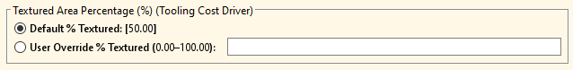
Textured Area Percentage – Set to 50% by default, as controlled by the cost model variable plant.defaultTextureAreaPercentage. An override option is also provided, as shown in this figure.
The rates that are used in tool texturing time calculations are:
-
toolBlastingRate – Time, in seconds, to bead blast 1 square meter of tool. The default value is 500 seconds.
-
toolChemicalEtchingRate – Time, in seconds, to etch 1 micrometer of texture depth. The default value is 3 seconds.
-
toolCleaningRate – Time, in seconds, to hand clean 1 square meter of tool. The default value is 2150 seconds.
-
toolDryingTime – Time, in seconds, to dry tool after cleaning. The default value is 1500 seconds, which is not dependent on part/cavity size.
-
toolMaskingRate – Time, in seconds, to mask 1 square meter of tool. The default value is 5285 seconds.
-
toolPhotoMaskUVExposureTime – Time, in seconds, to develop photomask. The default value is 1200 seconds. This field is not dependent on part/cavity size.
As a result of these enhancements, mold texturing is now reduced to approximately 3% of total mold cost, whereas previously it was between 6% and 14%. In general, deeper textures are expected to yield larger texturing cost changes.
Error Checking for Tooling Configurations
aPriori now checks for incompatible process setup options that result in an invalid plastic molding tooling configuration.
If you specify an invalid combination of plastic molding process setup options (PSOs) for the PSOs that are shown in this figure, aPriori now fails to cost the part.
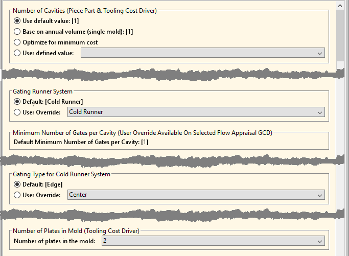
An invalid combination for a part that uses the plastic molding process group is:
-
Either the Number of Cavities is greater than 1 or the Minimum Number of Gates Per Cavity is greater than 1.
-
Gating Runner System is set to Cold Runner.
-
Gating Type for Cold Runner System is set to Center.
-
Number of Plates in Mold is set to 2.
More Accurate Material Cost Estimates via New Limits for Regrind Material
aPriori now provides more accurate estimates of Material Utilization and Material Cost by limiting the amount of regrind material to either the amount that can be produced by in-process scrap or a factory-level limit, whichever is smaller.
The cost model variable defaultRegrindAllowance provides a default factory-level limit on the maximum percent of regrind material that could be included in a part (set to 0.25 or 25% by default). In previous releases, aPriori calculated Material Utilization and Material Cost by assuming this amount of regrind material was used, even if the amount of scrap produced in the manufacture of the part (from sprues, runners, and scrapped parts) was lower than that value. Now by default, aPriori assumes that only the scrap produced in-process is available as regrind material.
As this figure shows, the process setup option Material Regrind Allowance now displays both the factory-level default and the calculated scrap. It allows you to override the percentage of regrind material used.
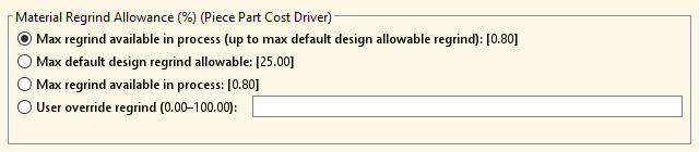
You can change the value to include a different amount of in-process scrap, some out-of-process scrap (if available), or a combination thereof. If the specified regrind percentage is greater than what is available in-process from the current part, a DFM message displays to confirm the specified amount of regrind material is actually available.
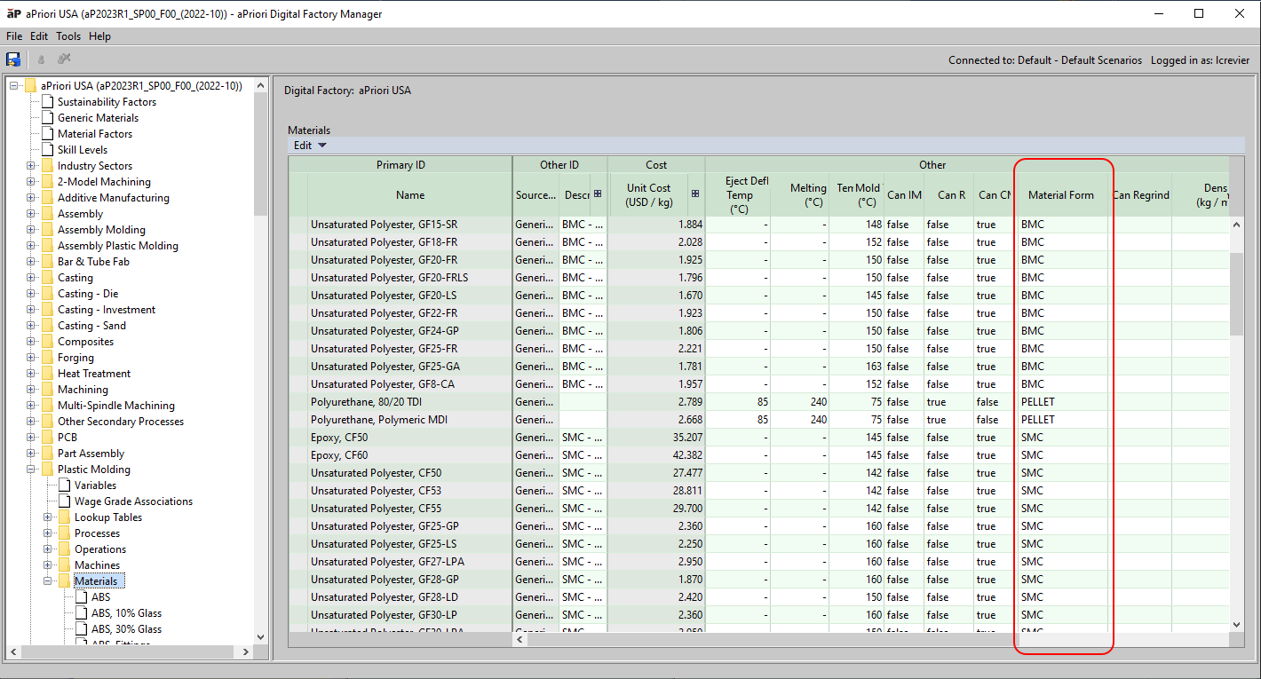
To indicate the materials that are poor candidates for regrind because they can adversely affect part quality or damage the grinding machine, the Material table now also includes a new field Can Regrind. For many applications, resins with long fibers (glass, aramid, carbon) and resins used for optical applications (such as polycarbonate) are considered non-regrindable. To retain the behavior from previous releases, the Can Regrind value is currently set to true for all materials in the aPriori Digital Factories and Regional Data Libraries. If a field is reset to false for a material in your own Digital Factories, aPriori displays a warning when you select a non-zero regrind percentage.
Bulk Molding Compound (BMC) Materials for Compression Molding
The Compression Molding process now supports thermosetting Bulk Molding Compound (BMC) Materials in addition to Sheet Molding Compound (SMC) materials.
The Compression Molding manufacturing process model was introduced in aPriori 2022 R1 to represent the thermoset forming of Sheet Molding Compound (SMC) materials in the Plastic Molding process group. aPriori 2023 R1 extends the Compression Molding model to also support thermosetting for Bulk Molding Compound (BMC) materials.
Both SMC and BMC can be used to make lightweight and cost-effective replacements for metal parts. BMC materials are similar to SMC materials in that both types consist of a thermosetting resin ( polyester, vinyl ester or epoxy) that is reinforced with chopped fibers ( glass, carbon or aramid).
There are, however, some key differences between BMC and SMC. BMC is typically lower cost and has shorter fiber lengths than SMC. Also, BMC is provided as a dough in a log or bucket while SMC is provided in sheets. BMC is lower strength but can flow more easily than SMC. This makes BMC an ideal material for complex, precise products that are potential alternatives for cast metal parts and sheet metal parts. Also, SMC tends to be used for higher-strength and larger-area parts, while BMC tends to be used for smaller parts that require more dimensional control, electrical resistance and flame-retardance. BMC is widely used for producing electrical insulation parts, motor brackets, automotive headlamp housings, and a variety of structural and protective components for different industries.
To support this enhancement, aPriori2023 R1, includes new materials, a new material classification, and new machines.
The aPriori Regional Data Libraries now contains 16 thermosetting BMC materials. For more information, see the What's New section of the aPriori Regional Data Libraries 2023-02 Release Notes.
As this figure shows, to differentiate between materials that can be used for Compression Molding and Injection Molding, the Plastic Molding Materials table has a new column Material Form which is set to BMC, SMC, or PELLET.
For materials designated as SMC, the charge preparation time accounts for the time required to remove the backing film from the material, which is not needed for BMC materials.
Smaller, lower-force hydraulic presses were added to the Compression Molding process because parts made with BMC are typically smaller than parts made with SMC. Eight new branded machines (from Accurl) and three small virtual hydraulic presses now are included in the aPriori 2023-02 Regional Data Libraries and aPriori 2023 R1 Digital Factories.
Limitations
-
The Compression Molding cost model does not fully support the use of thermoplastic BMC materials. Specifically, in practice compression molded BMC parts need additional cooling time that is not accounted for in the current model.
-
The Compression Molding cost model is available only for part CAD files. For an assembly CAD model that include small components (such as bearings or threaded inserts that are placed into the mold), to account for the quantity and cost of the included components, analyze the part file that represents the molded portion in the Compression Molding routing and use the process setup options Number of Inserted Components and Inserted Component Cost.
-
aPriori does not automatically account for the cost of any removable tooling inserts used to enable the forming of undercut geometry for compression molded parts.
Read Draw Direction from CAD File
aPriori 2023 R1 provides a new capability to use a CAD-defined draw direction to reduce analysis times and support highly-automated aPriori workflows.
Historically, aPriori has relied mainly on its powerful, proprietary algorithm for analyzing the geometry of molded parts (including plastic injection moldings, castings, and forgings) and determining the draw direction (mold-opening direction). This algorithm evaluates many candidate directions and selects one based on many criteria including the amount of undercut volume, alignment with various features on the part, flatness of the resulting parting line and required mold-opening height. In some cases the draw direction ultimately selected by aPriori , while reasonable, is different than the intended as-designed draw direction. Therefore, aPriori has also allowed you to specify the desired Draw Direction interactively. To do so, you had to inspect and, as needed, edit the draw direction and then recost the component using newly extracted GCDs.
In this release, instead of using the proprietary algorithm, you can configure aPriori to read and use designated datum references in the CAD file as the specified Draw Direction. Doing so eliminates the need to manually review and sometimes update the chosen draw direction, and also results in faster GCD extraction. This capability is available in aPriori Professional (for both on-premise and cloud deployments) and Cost Insight Design, (for cloud deployments), and is particularly useful for supporting high-volume lights-out workflows, which leverage aPriori Generate.
These process groups support reading Draw Direction from NX, CATIA, SolidWorks and Creo CAD models (including both Creo Direct Integration and CAD-I/cloud environments):
To leverage this capability, your organization must:
-
Adopt some company-standard ways of designating draw direction in your CAD models.
-
Configure the CAD Property Mapping File to identify the standard draw direction references.
An aPriori System Administrator can perform this step.
If a newly costed CAD model contains your company-standard draw direction references, aPriori will use them. Otherwise, it will fall back to using the proprietary algorithm for determining draw direction.
Draw direction references are defined for the entire aPriori deployment. aPriori provides flexibility in how draw direction may be designated, to support different naming conventions, languages, and modeling approaches used within different divisions of a company or standards which have evolved over time.
In general, aPriori supports specifying draw directions using these types of CAD entities:
-
An axis of a coordinate system with a custom name (for example, the Z-axis of the coordinate system named "Draw_Direction")
-
A datum axis with a given name
-
A datum plane with a given name (draw direction is perpendicular to the plane)
aPriori allows you to define multiple possible draw direction references in the CAD Property Mapping File as well as a priority order. When analyzing a part file, aPriori uses the highest-priority reference that exists in that part file as the draw direction. To capture when the draw direction is read from the CAD file, these new properties are available for the Parting Line GCD:
-
Mapped Draw Direction Name displays the full name of the CAD datum object that defines Draw Direction. If this field is empty, then draw direction was not read from the CAD model and the historical algorithm was used.
-
Mapped Draw Direction Type displays the type of the CAD datum object that defines Draw Direction. Possible values are Coordinate System, Axis, or Plane.
-
Mapped Draw Direction Axis is used only if Mapped Draw Direction Type is equal to Coordinate system and if so displays the axis of that coordinate system used to define draw (X, Y, or Z) otherwise no value is displayed in this field.