2-Model Machining Enhancements
2-Model Machining Automated Alignment Improvements
In aPriori 2024 R1 SP2, further improvements were made to the 2-Model Machining process group to automatically align the “source” and “finished” CAD models.
In the previous service pack, aPriori introduced sophisticated algorithms that compare the solid geometry of the source and finished CAD models in order to align them in 3D space, rather than relying only on their default coordinate systems. Please refer to the aPriori Pro 2024 R1 SP1 release notes for more information about these automated alignment algorithms. These algorithms worked well for a large majority of 2-Model part pairs, but some part pairs still were not aligned properly. In the 2024 R1 SP2 service pack, aPriori extended the algorithms to better align largely axisymmetric models with co-located features on both source and finished models.
Please see the following example to illustrate the improvements:
| Previous Behavior (aPriori 2024 R1 SP1) | New Behavior (aPriori 2024 R1 SP2) | |
|
|
|
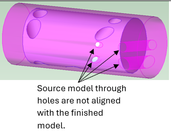
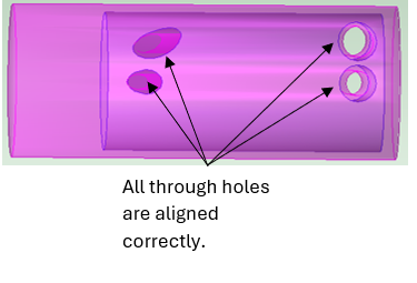
| The source model for this axisymmetric part includes some angled through pilot holes that must align with the enlarged through holes in the finished part model. Although aPriori previously aligned the finish model to fit within the source component, the algorithm failed to align the angled through holes correctly. | aPriori now fully aligns the source and finished models, including accurately positioning the source model's through hole within the corresponding hole of the finished model. |
Additionally, this release updates the feasibility rule that governs when the target (machined) part is considered significantly misaligned with respect to the source (net shape) part, and therefore fails to cost. Now models are considered misaligned if more than a specified percentage of the finished model’s volume (18% by default) protrudes outside the boundaries of the source model. Previous releases checked for misalignment based on the protruding surface area instead of volume.
As before, administrators can configure the value for this misalignment threshold with the cost model variable cadModelMisalignmentSensitivity. End users can override the default with the process setup option CAD Model Misalignment Sensitivity.