Edit Tolerances and Surface Roughness
aP Design allows you to add and edit tolerances manually after a CAD file has been imported or updated.
Tip
You can also define the aP Design default tolerance behavior for newly uploaded components; see Default tolerance and Surface Roughness Values. For a list of the tolerance types and CAD platforms that aP Design supports for this information, see How tolerances and surface roughness map to GCDs.
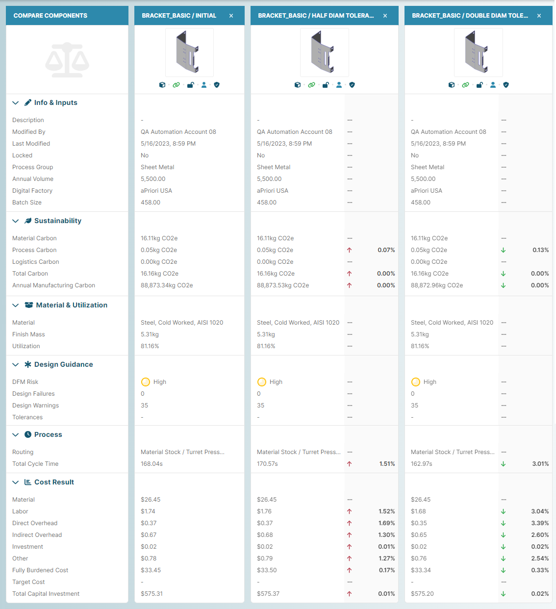
By creating and comparing tolerances for multiple scenarios for the same component, you can examine the impact of tolerances on cycle time, cost, manufacturability, and sustainability. For example, this scenario comparison shows the impact of applying half and double the initial tolerance values.
View and Edit Tolerances
You can view, edit, or add tolerances:
- For a single GCD
- For multiple GCDs
In both cases, the scenario that you edit the tolerances for must be private and analyzed.
Add or Edit Single-GCD Tolerances
- Open a successfully analyzed private scenario to the Evaluate tab.
-
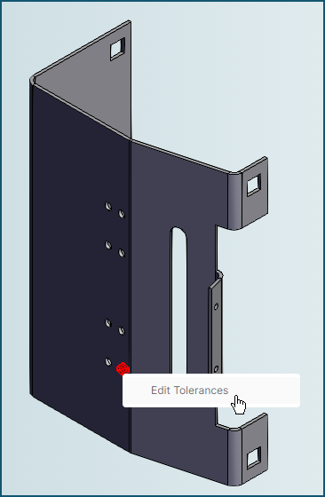
In the 3D viewer, on the component, select the feature that is associated with the GCD for which you want to add or edit a tolerance.
If the feature is associated with only one GCD, the feature becomes highlighted when selected. For example, because the edge of the bracket in this figure is associated with only one GCD, it becomes highlighted when selected:
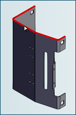
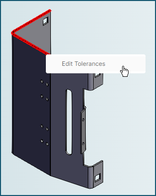
After the feature is highlighted, right-click it and then, in the context menu that appears, select Edit Tolerances:
Alternatively, if the feature is associated with more than one GCD, a list appears showing all the associated GCDs. For example, when a hole in the bracket is selected, a menu that contains two GCDs appears:
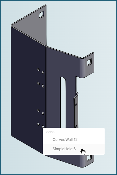
In this case, select the relevant GCD, right-click the highlighted feature and select Edit Tolerances.
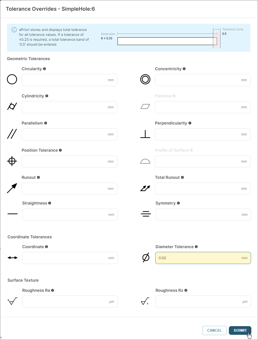
In either case, when you select Edit Tolerances, the Tolerance Overrides dialog for the selected GCD opens.
-
In the Tolerance Overrides dialog, add or edit one or more tolerances for the GCD, then click Submit.
To see the impact of the tolerance change, re-analyze the scenario.
Add or Edit Multi-GCD Tolerances
Caution
This method applies to GCDs that already have at least one tolerance applied.
- Open a successfully analyzed private scenario that contains at least one toleranced GCD to the Evaluate tab.
-
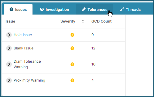
In the Design Guidance tile, click the OPEN button:
Tip
In the Design Guidance tile, the GCDs with Tolerances value is the number of GCDs that already have at least one tolerance.
-
In the Design Guidance explorer, open the Tolerances tab.
-
In the Tolerances tab, select a type of tolerance.
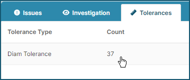
The toleranced GCDs are listed in the explorer and the associated features are highlighted in the 3D viewer.
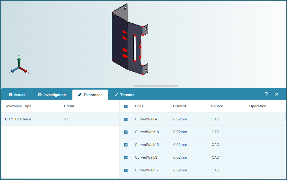
In the explorer, select one or more similar GCDs, click on the model in the 3D viewer, and then click Edit Tolerances.
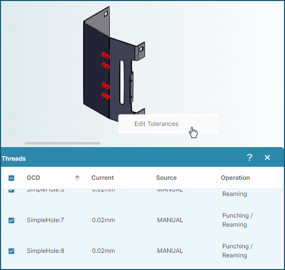
The Tolerance Overrides dialog for the selected GCDs opens.
-
In the Tolerance Overrides dialog, add or edit one or more tolerances for the GCD, then click Submit.
To see the impact of the tolerance change, re-analyze the scenario.
Usage Tips
-
You cannot manually delete a tolerance that was extracted from the Production and Manufacturing Information (PMI) in a CAD file. To nullify a tolerance that aPriori applied based on PMI, you can either:
- Delete that PMI from the CAD model and then update the CAD file.
- Relax the tolerance by manually replacing the existing value with a significantly larger or significantly smaller value, as applicable, that nullifies the effect of the tolerance.
-
If you manually specify a tolerance that is inappropriate (such as a runout on a flat planar face) or that is permissible in aP Design but not in aP Pro, or vice versa, a conflict may occur during a regularly scheduled automatic synchronization between aP Design and aP Pro. If a conflict occurs, the scenario will become unstable and will fail to analyze.
To avoid such a conflict, do not specify tolerances in aP Design that violate your organization's tolerances policies in aP Pro and vice versa.
To stabilize a scenario that is in an unstable state due to a tolerance issue, you can either:
- Specify an appropriate value for the problematic tolerance within aP Pro or aP Design
- Change your tolerance policy so that it does not apply the problematic tolerance and then update or re-import the CAD file
- Change or delete the tolerance in the CAD Model and then update or re-import the CAD file