3D Viewer
The Viewer on the Evaluate tab is an interactive display of a 3D representation of the open component.
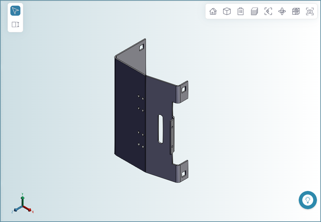
In addition to the 3D component representation, the Viewer contains these elements:
Toolbar

The tools available in the Viewer toolbar depend on the component type (part or assembly) and whether the scenario has been successfully analyzed.
| Tool | Name | Description: | Menu Items |
|---|---|---|---|
 |
Home | Set the zoom level to 100% and the global axis to the basis view (x=0, y=0, z=0). | – |
 |
Zoom All | Set the zoom level to 100%. | – |
 |
Analysis | Open the Analysis menu. The Analysis menu is available only for analyzed scenarios. The tools shown depend on the component type and the manufacturing process. |
 Active Axes Active Axes Bounding Box Bounding Box Cross Section Cross Section - Draw Direction - Draw Direction- Parting Line- Ram Direction  Flat Outline Flat Outline GCD Labels GCD Labels Component Labels Component Labels Source Model Source Model Turning Profile Turning Profile |
 |
Draw Mode | Opens the Draw Mode menu. |  Solid Solid Wire Frame Wire Frame Transparent Transparent |
 |
View | Opens the View menu which allows you to rotate the component to an isometric or standard view. |  Isometric Isometric Top Top Left Left Front Front Bottom Bottom Right Right Back Back |
 |
Sectioning | Section the component parallel to the X, Y, or Z plane. |  Cutting Plane x Cutting Plane x Cutting Plane y Cutting Plane y Cutting Plane z Cutting Plane z |
 |
View Mode | Open the View menu. |
 Global Axis Global Axis |
 |
Explode | Separate the components of an assembly. Available only for assembly scenarios. | – |
 |
Screen Capture | Capture and download the current view as a .png file, including current measurements and, if visible, the global axis. | – |
 |
Flow Appraisal | Select to show material flow visualizations, helping you identify potential short shot conditions in plastic molding scenarios. Use the Appraisal dropdown to switch between visualization gate placement options: Free, Long Side, and Short Side. Colors represent estimated cavity pressure, with black representing a short shot, or failure to completely fill the mold. |
– |
 |
Thickness Analysis | Select to view a representation of thickness distribution in plastic molding and casting scenarios. Spheres (points) are color-coded, ranging from blue (minimum thickness) to red (maximum thickness). The diameter of each sphere represents the relative thickness at that location. Switch between Overview(all points),Minimum(bottom 10%), and Maximum(top 10%) view options to focus on the most significant thickness points. Labeled values show the thinnest and thickest points for the current view and are informational, not an indication of Design Guidance issues. |
– |
Global Axis
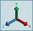
The global axis is a 3D x, y, z reference axis that is aligned to the isometric view of the component in the viewer. You can hide and unhide the global axis by using the View Mode menu in the viewer toolbar.
To hide or unhide the global axis, in the viewer Toolbar, click the View Mode button and then, in the dropdown menu, select the Global Axis.
Measurements Toolbar
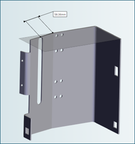
The measurements toolbar allows you to make point-to-point measurements in part and assembly components:

You can measure distances in a single part, and between points on different parts. You can make multiple measurements for a component.
To measure distances:
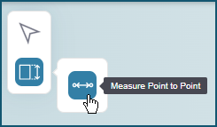
-
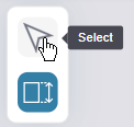
Click the measurement button and then click the point to point button.
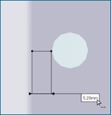
-
Click the location for the first end point, then click the location for the second end point, drag and drop first the measurement lines, and then the measurement, to your desired location in the viewer.
To clear displayed measurements, click the Select button.
Tip
To measure the distance between two points in the same plane, use the intersection tool with the measurement tool.
Saving Measurements
Measurements are temporary. To save a permanent record of measurements, use the screen capture tool (in the Toolbar).