What’s new in aPriori Electronics Costing 2020-03
Electronics Costing Release Notes 2020-03
Overview of changes
The changes in this release allow you to cost a higher percentage of a PCBA BOM with less manual effort by filling gaps in data collected from Electronics Data Collection interface with default values stored in the VPE.
Electronics Data Collection
There are two major updates for the Electronics Data Collection interface (EDC):
-
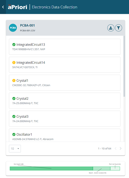
User experience – The status bar for a BOM now represents three statuses, giving the user insight into the actual part match rate with the SiliconExpert database. Previously, the status bar in EDC only showed the status of parts that had a match in SiliconExpert and had complete data required for costing. Now the status bar shows parts that have:
- A match and complete data
- A match and partial data or multiple matches
-
No matches
Note:
2020-03 Electronics Data Collection interface improvements require upgrades to:
- PCBA and Wire Harness cost models
- PCBA and Wire Harness costing macros
- User Defined Attributes (UDAs) For more information, please contact your aPriori account team.
-
Export behavior – The BOM export from EDC now includes data for parts that have a match but do not have all of the data required for costing. Previously, only parts that had a match and all required data had data exported into the BOM file. This change increases the amount of data being exported but does not change the output data format. The BOM file Parts that have incomplete data are included in the BOM file with the Incomplete status.
Note No upgrades, preference, or system changes are required for this enhancement.
PCBA Cost Model
Major Changes
To take advantage of additional data that is exported from EDC, some changes have been implemented in the PCBA cost model.
For parts that have partial data exported, the PCBA cost model can now apply default values for the missing data fields based on the classification data for a component. The Component Classification Defaults table is the source of the default values that are applied. The default values are used only when:
- A value is not available in the BOM file for that field
- A value is not available in the component library for that field
- The user specifies that VPE defaults should be considered
- The component has a classification that is included in the lookup table componentClassificationDefaults
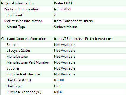
To identify the source of specific values in a costed PCBA, users can navigate to the custom outputs for a given part. For example, the figure shows that Pin Count was taken from the BOM file, the Mount Type was taken from the Component Library, and the Unit Cost (USD) was taken from VPE defaults and that the VPE default preference was for the lowest cost.
To take advantage of the additional data exported from EDC, each of these changes must be implemented in the customer environment:
- Define a new User Defined Attribute (UDA) named PCBA – Component Classification. This UDA stores the component classification that is extracted from SiliconExpert.
- Update the PCBA BOM Loader mapping to map the Classification column from an EDC export to the PCBA – Component Classification UDA.
- Update the PCBA costing macro to include two new input fields that enable the user to specify whether they want to use default values from the componentClassificationDefaults lookup table for physical data and cost data independently.
- Update the cost model to pull values from the componentClassificationDefaults table on a field by field basis.
The lookup table that drives the default values for components, componentClassificationDefaults, has been populated with default values for 53 different classification. To determine which default values to use:
- aPriori iterates through the lookup table in the order of the field Search Index in the lookup table
-
aPriori evaluates the value of the UDA PCBA – Component Classification to see if the string includes the value from the Component Classification Includes field in the lookup table. If:
-
There is a match, the values from that row are used as needed.
-
There is not a match, the next Search Index is considered until there is a match.
-
There are no matches in the table, the field does not get a value and the component fails. This is the default behavior.
It is also possible to use default values for any parts that do not have a match in the component classification table by modifying the lookup table. However, because this technique is not driven by any underlying intelligence, and very broad assumption is assumed.
To automatically fill in missing data when there are nor matches in the table:
-
Add a row to the lookup table componentClassificationDefaults with the values.
-
Enter DefaultValue in the Component Classification Includes column.
-
Enter a value greater than all other search index values in the Search Index column.
-
Enter the default values you would like to apply to unmatched parts in the Pin Count, Mount Type, and Unit Cost columns.
-
Minor Changes
Several minor changes have also been made to improve the PCBA cost model:
- To improve the transparency of cost calculations, the purchase variance applied to the unit cost is now exposed as a custom output. Purchase variance is used to account for discounts your company may receive on components based on factors such as buying power or negotiating leverage.
- The custom output for pin count has been fixed so that it represents the pin count of a single component. Previously this value was shown as the pin count of the part multiplied by the quantity of that part in the assembly, which was misleading.
- Unit type no longer needs to be populated for components. if no unit type is provided then a unit type of Each is assumed
Component Classification Defaults table
| Search Index | Component Classification Includes | Pin Count | Mount Type | Unit Cost | Unit Type |
|---|---|---|---|---|---|
| 1 | Resistor Fixed Single-Surface Mount | 2 | Surface Mount | 0.05 | Each |
| 2 | Resistor Fixed Single-Through Hole | 2 | Through Hole | 0.25 | Each |
| 3 | Resistor | 2 | Surface Mount | 0.05 | Each |
| 4 | Variable Capacitors | 2 | Surface Mount | 2.50 | Each |
| 5 | Capacitor Networks and Arrays | 8 | Surface Mount | 0.05 | Each |
| 6 | Capacitor | 2 | Surface Mount | 0.10 | Each |
| 7 | Connector | 6 | Through Hole | 5.00 | Each |
| 8 | Specialized Programmable Logic | 20 | Surface Mount | 5.00 | Each |
| 9 | Field Programmable Gate Arrays - FPGAs | 144 | Surface Mount | 15.00 | Each |
| 10 | LED | 3 | Surface Mount | 1.50 | Each |
| 11 | Switch | 8 | Surface Mount | 1.25 | Each |
| 12 | Varistors | 2 | Through Hole | 0.90 | Each |
| 14 | Gas Discharge Tubes - GDTs | 2 | Surface Mount | 0.50 | Each |
| 16 | ESD Suppressors | 2 | Surface Mount | 0.25 | Each |
| 17 | TVS | 2 | Surface Mount | 0.15 | Each |
| 18 | Overcurrent Protection | 2 | Through Hole | 0.50 | Each |
| 19 | Clock Generators and Synthesizers | 16 | Surface Mount | 5.00 | Each |
| 20 | Direct Digital Synthesizers - DDS | 16 | Surface Mount | 15.00 | Each |
| 21 | Timing | 8 | Surface Mount | 2.00 | Each |
| 22 | Clock Buffers and Drivers | 24 | Surface Mount | 3.50 | Each |
| 23 | Controller Area Network | 8 | Surface Mount | 0.75 | Each |
| 24 | Connector | 8 | Through Hole | 7.50 | Each |
| 25 | Data Acquisition | 24 | Surface Mount | 20.00 | Each |
| 26 | RF FETs | 3 | Surface Mount | 25.00 | Each |
| 27 | Diodes, Transistors and Thyristors | 3 | Surface Mount | 1.00 | Each |
| 28 | Drivers and Interfaces | 16 | Surface Mount | 2.50 | Each |
| 29 | Relays and Solenoids | 8 | Surface Mount | 4.00 | Each |
| 30 | Amplifiers | 8 | Surface Mount | 8.00 | Each |
| 31 | Comparators | 16 | Surface Mount | 4.00 | Each |
| 32 | Inductor Leaded | 2 | Through Hole | 0.90 | Each |
| 33 | Inductor Surface Mount | 2 | Surface Mount | 0.25 | Each |
| 34 | Transformers | 8 | Surface Mount | 2.50 | Each |
| 35 | Filters | 6 | Surface Mount | 2.50 | Each |
| 36 | Memory | 48 | Surface Mount | 12.00 | Each |
| 37 | Microcontrollers and Processors | 324 | Surface Mount | 48.00 | Each |
| 38 | Optoelectronics | 8 | Surface Mount | 1.00 | Each |
| 39 | Crystals and Resonators | 2 | Surface Mount | 0.25 | Each |
| 40 | Oscillators | 10 | Surface Mount | 3.00 | Each |
| 41 | Voltage References | 8 | Surface Mount | 0.75 | Each |
| 42 | Application Specific | 16 | Surface Mount | 1.75 | Each |
| 43 | DC to DC Conversion | 12 | Surface Mount | 15.00 | Each |
| 44 | Power Management | 16 | Surface Mount | 2.50 | Each |
| 45 | Programmable Devices | 256 | Surface Mount | 15.00 | Each |
| 46 | Sensors and Transducers | 16 | Surface Mount | 3.50 | Each |
| 47 | Standard and Specialty Logic | 16 | Surface Mount | 0.50 | Each |
| 48 | Transceivers | 20 | Surface Mount | 0.75 | Each |
| 49 | RF ICs | 16 | Surface Mount | 8.50 | Each |
| 50 | RF Amplifiers | 4 | Surface Mount | 20.00 | Each |
| 51 | RF Modules | 8 | Surface Mount | 3.00 | Each |
| 52 | Couplers | 4 | Surface Mount | 2.00 | Each |
| 53 | RF Attenuators | 16 | Surface Mount | 3.50 | Each |