Draw direction mappings
If you define an appropriate CAD mapping file, aPriori can extract draw direction directly from a part's CAD file, provided that the file contains one of the following named datum objects:
- Datum coordinate system that has a coordinate axis co-directional with the intended draw direction
- Datum axis that is co-directional with the intended draw direction
- Datum plane whose normal is co-directional with the intended draw direction
(Note that there are some limitations associated with CAD-I.)
This section covers the following topics:
- Draw Direction Mapping Basics
- Complex Draw Direction Mapping Files and Precedence Rules
- Process Groups that Support Draw Direction Mapping
- Disabling Draw Direction Mapping
- CAD Formats and Limitations for Draw Direction Mapping
- Parting Line Properties Related to Draw Direction Mapping
Draw Direction Mapping Basics
To enable aPriori to read draw direction from CAD, create an mapping file in XML that specifies the names of the datum objects to be used as draw direction sources. Then import the XML with the System Administration menu item *File > Import > CAD Property Mapping File*.
Note:
For process groups that should not use the mapping and should not extract draw direction from CAD, set the site variable drawDirectionMappingEnabled to false. For process groups that should use the mapping and extract draw direction from CAD, ensure that the site variable drawDirectionMappingEnabled is set to true (the default in starting point Digital Factories).
For a coordinate axis, the mapping file must specify the name of the axis as well as the name of the datum coordinate system that the axis is part of. Here is a simple example:
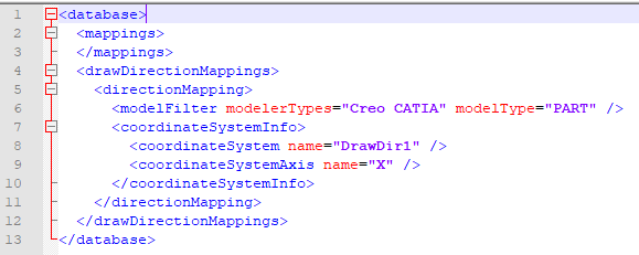
The mapping in the example above designates as draw direction the coordinate axis named X in the coordinate system named DrawDir1. Note the following:
-
The modelFilter element specifies the types of CAD file to which the mapping applies. The modelerTypes attribute specifies a space-separated list of values. Possible values are:
- CATIA
- Creo
- NX
- SolidWorks The value of the modelType attribute must be Part for draw direction mapping.
-
The coordinateSystemInfo element has two subelements:
- The coordinateSystem element specifies the coordinate system name, DrawDir1, as the value of its name attribute.
- The coordinateSystemAxis element specifies the axis name, X, as the value of its name attribute.
Here is an example that specifies a datum axis name in order to designate the draw direction:
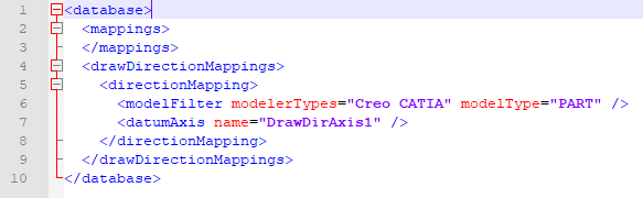
This mapping designates as draw direction the datum axis named DrawDirAxis1. The datumAxis element specifies the axis name, DrawDirAxis1, as the value of its name attribute.
Here is an example that specifies a datum plane name in order to designate the draw direction (normal to the plane):
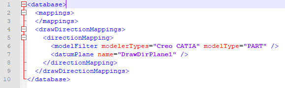
This mapping designates as draw direction a normal to the datum plane named DrawDirPlane1. The datumPlane element specifies the axis name, DrawDirPlane1, as the value of its name attribute.
Note that you use short names to specify the names of datum objects.
When aPriori reads draw direction from CAD, information about the datum object used can be found in the values of certain Parting Line properties.
The elements of the XML mapping file are described in detail in CAD Mapping tag reference.
Complex Draw Direction Mapping Files and Precedence Rules
If the datum object names used to designate draw direction vary from CAD file to CAD file, your drawDirection element can have multiple coordinateSystemInfo, datumAxis, or datumPlane elements. Moreover, if the type of datum object used to designate draw direction differs from CAD file to CAD file, your directionMapping element can have a combination of coordinateSystemInfo, datumAxis, and datumPlane elements. In addition, If there are different rules for different modelers, your drawDirectionMappings element can have multiple directionMapping elements. Here is an example:

With default precedence rules (see below), the example above directs aPriori to select draw direction as follows, if the modeler is Creo or CATIA:
- If the CAD file has a coordinate system datum object named DrawDir1, select that system's coordinate axis named X, if it exists.
- Otherwise, if the CAD file has a coordinate system datum object named DrawDir2, select that system's coordinate axis named X, if it exists.
- Otherwise, if the CAD file has a coordinate system datum object named DrawDir, select that system's coordinate axis named Y, if it exists.
- Otherwise, if the CAD file has a coordinate system datum object named DrawDir1, select that system's coordinate axis named Y, if it exists.
- Otherwise, if the CAD file has a datum axis named DrawDirAxis1, select that axis.
- Otherwise, if the CAD file has a datum axis named DrawDirAxis2, select that axis.
- Otherwise, if the CAD file has a datum plane named DrawDirPlane1, select a normal to that plane.
- Otherwise, if the CAD file has a datum plane named DrawDirPlane2, select a normal to that plane.
If a CAD file contains multiple datum objects of the specified types with the specified names, aPriori selects a draw direction using the following precedence rules:
- By default, if mapped coordinate systems are present in the CAD file, they are used as the draw direction source. If there are no coordinate systems, aPriori searches for mapped axes, and if no axis is found, then mapped planes are analyzed. Users can override this default precedence with the site variable drawDirectionMappingOrder. Choose a comma-separated list of values; the default is Coordinate System, Axis, Plane.
- If site variable drawDirectionMappingPreferActiveEntities is set to true, then active datum objects take precedence over hidden objects. In this case, if active objects are present in the model, only they are considered as the draw direction source; if only hidden objects are present, they are used as the draw direction source. By default, this site variable is set to false, so active and hidden entities have the same effect on draw direction mapping.
- If several datum objects of the same type are selected as the draw direction source using previous criteria, then the object that is declared first in the mapping file is selected.
- If several datum objects of the same type have the same user selected name, these objects are sorted by full name, and the first one is selected as draw direction source.
Note:
In mapping files, names of datum objects and coordinate axis identifiers are case insensitive.
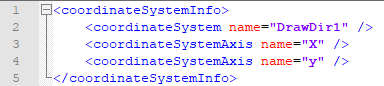
Note that aPriori ignores a coordinateSystemInfo element if any of the following hold:
-
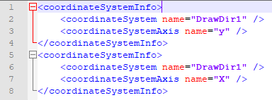
It has two or more differently named coordinateSystemAxis sub-elements. Here is an example:
-
It has no coordinateSystemAxis sub-element.
- It has a coordinateSystemAxis sub-element whose name is not X, x, Y, y, Z, or z.
In addition, aPriori ignores a coordinateSystemInfo element, S1, if there is another coordinateSystemInfo element, S2, such that both the following hold:
- S1 and S2 have coordinateSystem sub-elements with the same name.
- S1 and S2 have coordinateSystemAxis elements with different names.
Here is an example:
See also CAD Mapping tag reference.
Short Names and Full Names
Note, that the user needs to specify the short names of the datum object--the ones that are controlled by the user--not the full names controlled by the CAD system. For example, for CATIA, a full name of a coordinate system is Part1|Axis Systems|csys1, that is, <part-name><tree-section><object-name>, and the user must specify name csys1 in the mapping file.
Process Groups that Support Draw Direction Mapping
Draw Direction mapping is supported for the following process groups:
- Casting - Die
- Casting – Investment
- Casting – Sand
- Forging
- Powder Metal
- Plastic Molding
Disabling Draw Direction Mapping
You can disable draw direction mapping for all process groups by setting site variable drawDirectionMappingEnabled to false (it is set to true in starting point Digital Factories).
CAD Formats and Limitations for Draw Direction Mapping
The following four formats of CAD file support draw direction mapping: Creo (Including Direct Integration), CATIA, NX, and SolidWorks. Specific features and limitations of each modeler are described below:
- SolidWorks: the full name of a datum object in SolidWorks is the same as the user-specified name (for example, Csys1). All datum objects are fully supported for SolidWorks parts.
- Creo: the full name of a datum plane for Creo parts opened in CAD-I is <part-name><plane-name> (for example, PART1|PLANE1). For coordinate systems in CAD-I and all datum objects in Direct Integration, the full name is the same as user-specified name (for example, CSYS1). Currently, CAD-I has limited support of Creo parts: datum axes are not supported, and both active and hidden datum objects are considered as active. In Direct Integration all datum objects are fully supported.
- CATIA: the full name of a datum object in CATIA is <part-name><tree-section><object-name> (for example, the full name of a coordinate system is Part1|Axis Systems|csys1). All datum objects are fully supported for CATIA parts.
- NX: the full name of a datum object in NX is <object-type> (<entity-number>) < object -name> (for example, the full name of a coordinate system is Datum Coordinate System (7) CSys1). Currently, for NX, both active and hidden axes are considered as active.
Parting Line Properties Related to Draw Direction Mapping
If aPriori reads draw direction from CAD for a particular part, the following properties of the Parting Line GCD are populated:
- Mapped Draw Direction Name: the full name of the datum object that defines draw direction.
- Mapped Draw Direction Type: the type of datum object that defines draw direction. Possible values are Coordinate system, Axis, and Plane.
- Mapped Draw Direction Axis: the axis of the coordinate system used to define draw direction. If the value of Mapped Draw Direction Type is Coordinate system, this property is equal to X, Y, or Z. Otherwise, it is empty.
If the draw direction is not extracted from CAD, these three properties are not populated and remain empty.