Use the Component Viewer
The Component Viewer provides a three-dimensional image of a part or an assembly. The image is automatically saved to the database and is available whenever the part or assembly is opened
Note:
You can only access the Component Viewer for a costed component.
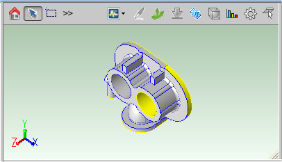
Component Viewer Buttons
Use the following control icons using the buttons on the left of the toolbar):
| Icon | Function | Use |
|---|---|---|
 |
Reset | Click this icon to reset the image to its original state. |
 |
Select | Click this icon, then click anywhere on the image to select a specific Geometric Cost Driver (GCD). The selected GCD is highlighted in the Geometric Cost Drivers table and information related to this GCD is displayed. To select multiple GCDs of the same type, for example, multiple holes or welds, press the Ctrl key and click GCDs one by one. To deselect a selected GCD, press the Ctrl key and click the selected GCD. |
 |
Marquee Selection | Use this tool to draw a box on the screen and select all GCDs within that box of the same type. from Bending/Forming, Volume, Holes, Surfaces, Joining, Other, Not Supported |
 |
Zoom | To zoom in, click this icon, press the left mouse button and move the mouse toward you. To zoom out, click this icon, press the left mouse button and move the mouse away from you. Alternatively, move the middle mouse button wheel forwards and backwards to zoom in and out. |
 |
Pan | To move to a certain part of an image, click this icon, press the left mouse button, then move the image by moving the mouse. Alternatively, press the Shift key and the middle mouse button to move the image. Panning is especially useful when the image is zoomed out so that it does not fit into the Component Viewer. |
 |
Rotate | To rotate an image, click this icon, press the left mouse button, and move the mouse. Alternatively, press the middle mouse button and move the mouse |
 |
Render mode | To change the way the image is displayed, click this icon and select Solid, Wireframe, Transparent. |
|
Select | Click this icon, then click anywhere on the image to select a specific Geometric Cost Driver (GCD). - The selected GCD is highlighted in the Geometric Cost Drivers table and information related to this GCD is displayed. - To select multiple GCDs of the same type, for example, multiple holes or welds, press the Ctrl key and click GCDs one by one. - To deselect a selected GCD, press the Ctrl key and click the selected GCD. |
|
Marquee Selection | Use this tool to draw a box on the screen and select all GCDs within that box. |
The viewer also provides the following shortcuts when you click on the origin symbol in the lower left of the view:
- Click on the origin symbol to toggle the part between different axes based on the position of the cursor relative to the axes on the origin.
- Click and hold on the origin to rotate about its center point
- CTRL-click and hold on the origin to enable zooming in or out.
- SHIFT-click and hold on the origin.
To change the size of the component viewer, click the right bottom corner of the component viewer and drag it with your mouse cursor.
Edit GCDs
Use the following functions (using the buttons on the right of the toolbar) to display and edit GCDs:
Note:
Functions vary depending on the Manufacturing Process Group.
- Analysis: Select characteristics to display for a part component. See Analysis: Display Part Characteristics.
- Welding: Create a virtual weld for an assembly component. See Add Virtual Welds.
- Setup Axis: Display setup and turning axes, modify setup axes, and limit turning axes. See Edit Part Setups for Machining.
- Stock Form and Alignment: Display and edit the automatically-chosen stock shape and alignment. See Define Stock Form and Alignment.
- Draw Direction/Ram Direction: Manually select the draw direction (for most molding and stamping process groups), ram direction (for Transfer Die), or build direction (for Additive Manufacturing). See Define Draw Direction.
- Geometry Analysis: Identify which GCDs have properties or characteristics that drive costs. See Show a Part's Heat Map (Geometry Analysis)
Cost Model Functions
-
Gear Definition: Display the Gear Definition dialog, if displaying a part that includes gears, flutes, splines, or sprockets.
See the "Working with Gears, Splines, Sprockets, and Flutes" section of the aPriori Cost Model Guide for more information.
-
Set Main Surface for Sheet Metal Parts: Display the Set Main Surface dialog, enabled if displaying a sheet metal part.
See the " Main Surface for Hard Tooled Sheet Metal " section of the aPriori Cost Model Guide for more information.
-
Flattening Options: Displays the Flattening Options: dialog that is only enabled when displaying a sheet metal part. See the "Flattening" section of the aPriori Cost Model Guide for more information.
Use Right-click Menu Commands
Right-click anywhere in the Component Viewer to access Component Viewer Commands for the selected GCD or part:
- Edit Operation: Opens the Geometric Cost Driver Editor.
- Remove: Deletes the selected virtual welds or user-created setup axes.
- Edit Tolerances...: Opens the Tolerance Editor.
- Auto-merge: Auto-merges an ComboVoid GCD that has been unmerged using the Unmerge command.
- Unmerge: Unmerges a SimpleHole or a MultiStepHole GCD from a Void GCD in a ComboVoid GCD.
- Viewer: Opens the list of the Component Viewer controls.
- Tools: Opens the list of the Component Viewer tools for that Primary Process Group.
The following additional commands are also available when selecting parts in an assembly:
- Initialize: Initializes the selected parts or assemblies. Every part in the selection is initialized to the same process group, Digital Factory and production settings.
- Open: Opens a selected part in a new tab.
- Save: Saves any changes in the selected parts or assemblies.
Specifying 2D Images for virtual components
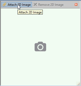
If you have a unlocked virtual scenario with no 3D image extracted from a CAD model, you can associate a image with the component:
-
Click the Attach 2D Image icon in the upper-left corner of the viewer.
-
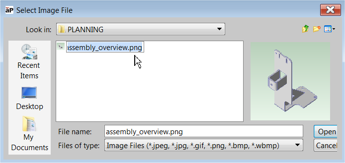
Use the Select Image File dialog to navigate to the image file that you wish to associate with the component.
Note:
You can also associate image files with CAD-less components when you define the component, or through the Bulk Loader or BOM. You can also attach or delete an image using Scenario > Attach 2D Image and Scenario> Remove 2D image.