Dimensional tolerances
aP Pro does not explicitly support traditional dimensional tolerancing of features. For example, on the part below, you can directly define the perpendicularity, diametrical, position, and profile of surface tolerances on the associated features. However, there is no direct way to define the +/- 0.01 tolerance between the bottom of the hole and the flat on the right side of the part.
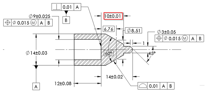
The best practice for accounting for these tolerances is using an equivalent profile of surface tolerance in place of the dimensional tolerance. The dimensional tolerance in this case controls the distance between the two features. This can be captured by applying a 0.01 profile of surface tolerance (half of the total dimension tolerance) on the planar faces that define the distance. By putting this tolerance on both features, the cost model can account for the controlled machining (or specialized finishing operations) required to accomplish these faces.
Note that if a feature falls under multiple dimensional tolerances, the tightest equivalent profile of surface tolerance should be used for the feature. In the example above, the face at the bottom of the hole has several dimensional tolerances applied (12 +/- 0.08, 10 +/- 0.01, 14 +/- 0.02). Accordingly, you would apply a profile of surface tolerance of 0.01 (the tightest dimensional tolerance called out) to the face at the bottom of the hole.
The cost model also accounts for a “Tolerance (Coordinate)” tolerance type. Generally, the tolerance types utilized in aPriori, such as flatness, profile of surface, and so on, connect directly to GD&T tolerance types. The one exception is the tolerance type “Tolerance (Coordinate).” This tolerance is intended to capture tolerances on the dimensions of a feature that cannot be entered via the prior workflow. It can also be used as a catch all to capture a tolerance driving additional machining time on a feature that does not fit into one of the specific GD&T categories.