Creo
For Creo direct integration only, aPriori extracts Diameter tolerance, Surface Roughness, cosmetic threads, and GD&T callouts.
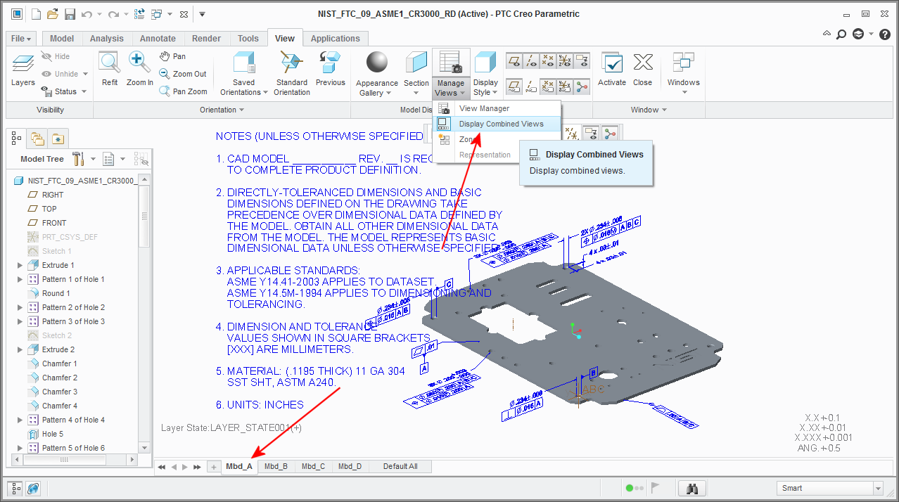
Displaying existing annotations By default, Creo turns off the display of most annotations to simplify the display. If you are opening a part that contains PMI (such as the NIST PMI test models available from http://www.nist.gov), you might need to turn on the display of these annotations.
Using a NIST test part as an example
- Go to the View tab, then click Manage Views > Display Combined Views.
-
At the bottom of the screen, click Mbd_A.
Creating tolerance annotations in Creo
Creating PMI annotations in Creo requires that you select surfaces and locations in a very specific order. The initial steps are intuitive, but the final steps are less obvious, as you might have one or two dialog boxes open with no clear direction about how to complete the operation.
The following steps walk you through an annotation procedure. Note that this is not necessarily the best or only way to add a geometric tolerance to a Creo model. It is intended only as a sample path to help users exploring this functionality for the first time. Please refer to official Creo technical support, training, and documentation resources for recommended procedures and best practices.
-
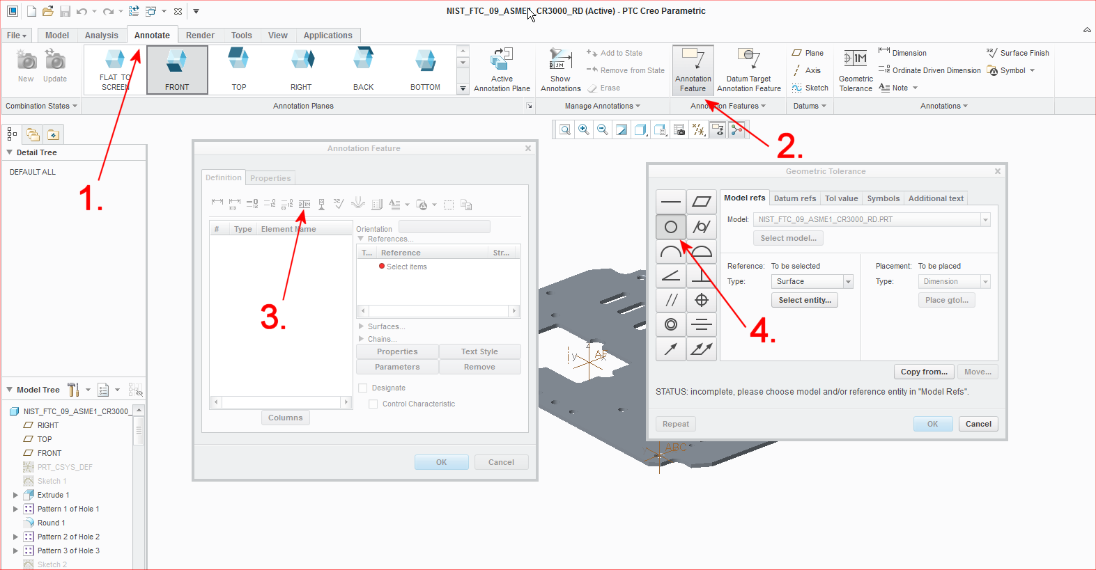
Click the Annotate tab (1), then click Annotation Feature (2).
-
In the Annotation Feature window, click the Geometric Tolerance icon (3), and in the Geometric Tolerance window.
-
Click the type of annotation you wish to create: in this example, “Circularity” (4).
-
-
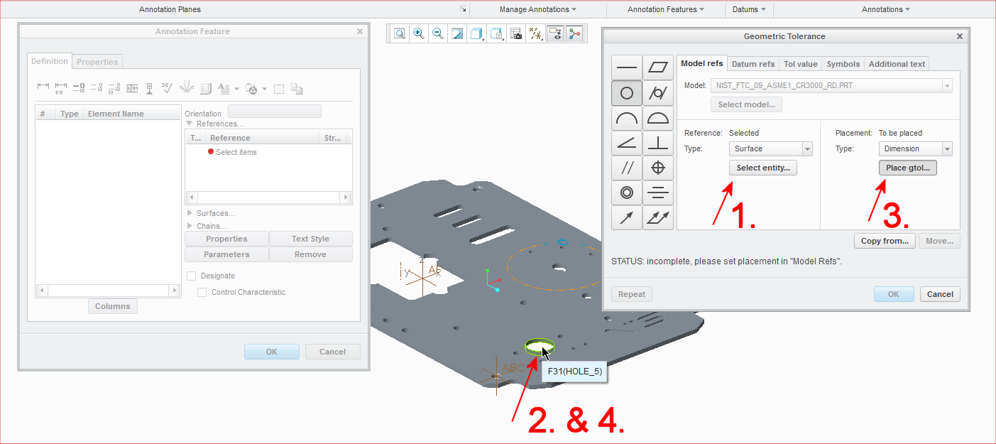
In the Geometric Tolerance dialog box, click Select entity (1),
-
Click the surface to be associated with the tolerance (2).
-
Click Place gtol (3)
-
Click the associated surface (4).
-
-
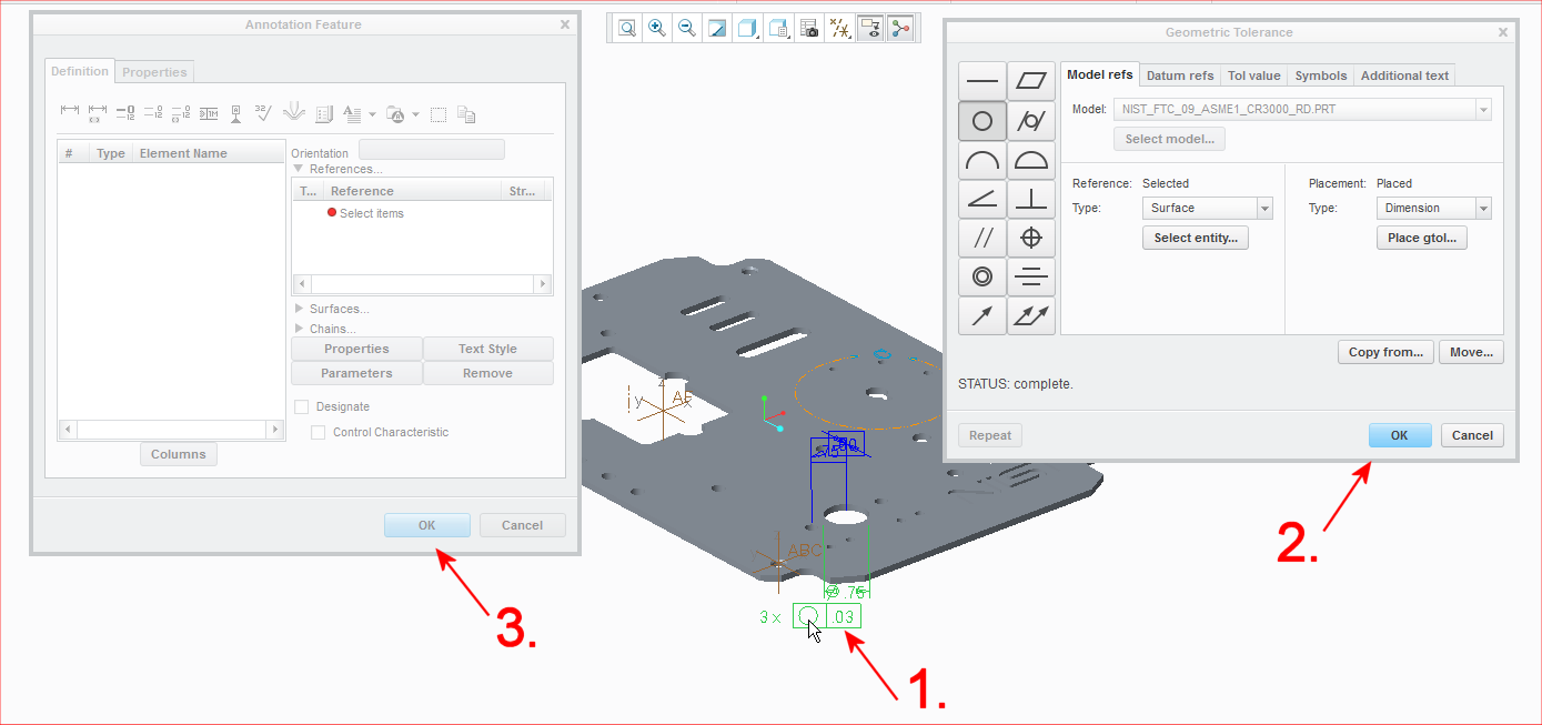
Select the dimension that was just added to the surface, and then click OK in both the Geometric Tolerance dialog box and the Annotation Feature dialog box.
-
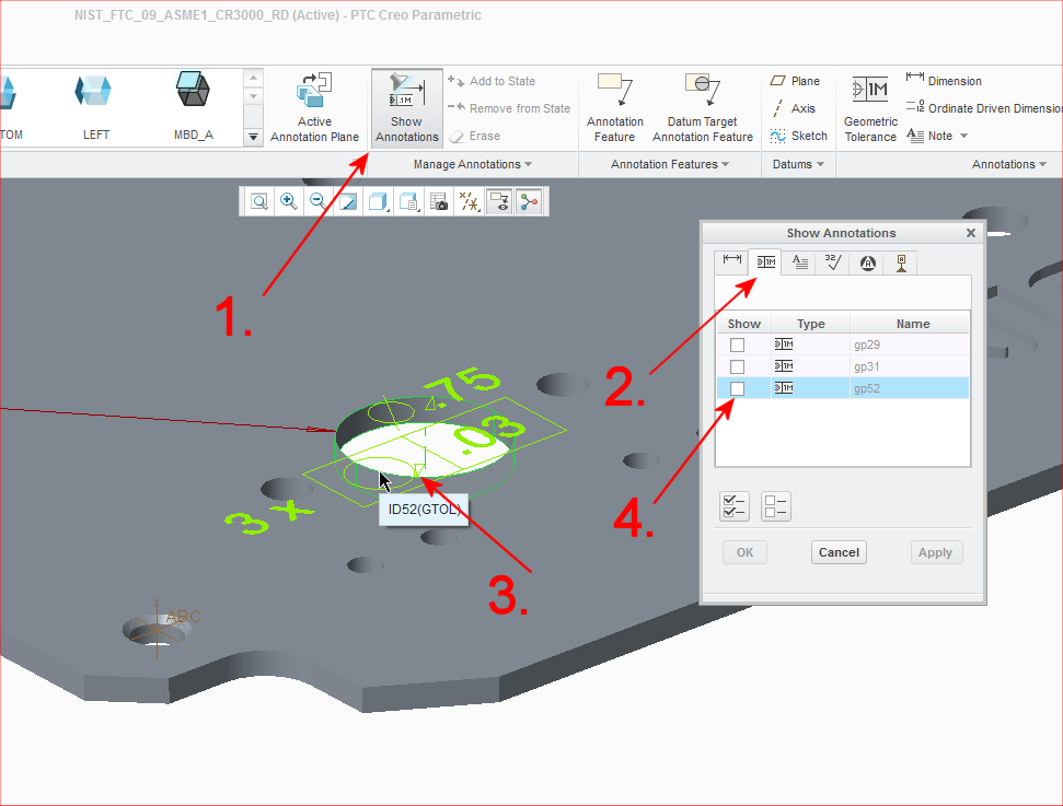
When you finish creating the annotation, you may need to turn on its display. If so, click Show Annotations (1)
-
Click the Geometric Tolerances tab in the Show Annotations dialog (2)
-
Click the annotation you wish to display (3).
-
Select its checkbox (4).
-
Click Ok when done.
-